Porous gas diffusion electrode for fuel battery and preparing method thereof

A gas diffusion electrode and fuel cell technology, applied in battery electrodes, electrical components, circuits, etc., can solve the problems of reducing the limit current and power density of fuel cells, restricting the performance of fuel cells, and low utilization rate of electrochemical catalysts. The effect of enhancing the proton transfer capacity and the use efficiency of the catalyst, improving the performance of the air cathode, and enhancing the gas mass transfer capacity

Inactive Publication Date: 2006-09-06
SUNRISE POWER CO LTD
View PDF4 Cites 2 Cited by
  • Summary
  • Abstract
  • Description
  • Claims
  • Application Information

AI Technical Summary

Problems solved by technology

The third method is that the catalyst is first mixed with PTFE to prepare a catalytic layer, and then sprayed on the above-mentioned catalytic layer with a conductive ionic resin to realize the three-dimensionalization of the catalytic layer (see US P-4876115 for details), which is a traditional hydrophobic electrode preparation process; this process The advantage is that the preparation process is simple and the repeatability is good. The disadvantages are that the contact surface between the conductive ion polymer and the electrochemical catalyst is small, the utilization rate of the electrochemical catalyst is low, and the proton conduction resistance is large, which restricts the performance of the fuel cell.
[0004] The biggest defect of the above-mentioned several processes is that under the condition of high current density operation, the mass transfer capacity of the gas, especially when air is used as the oxidant, is insufficient, which reduces the limiting current and power density of the fuel cell operation.

Method used


Image

  • Porous gas diffusion electrode for fuel battery and preparing method thereof
  • Porous gas diffusion electrode for fuel battery and preparing method thereof
  • Porous gas diffusion electrode for fuel battery and preparing method thereof

Examples


Embodiment 1

[0023] Example 1: An electrode with a two-layer composite catalytic structure was prepared by an electrostatic spraying process.

[0024] 1) Take a piece of 5Cm 2 Prepared diffusion layer (self-made diffusion layer of Toray carbon paper) or conductive ionic polymer resin film (Nafion TM 112 film 50um), according to 0.60mg catalyst / cm 2 Diffusion layer or conductive ionic polymer resin film, weigh John matthey Pt / C catalyst (Pt loading 0.3mg / cm 2 ), put into a beaker, add a small amount of deionized water to soak the catalyst, press 50ml absolute ethanol / g catalyst, add absolute ethanol. Ultrasonic oscillation, stirring for 2 minutes, the feed liquid is black ink; according to the weight ratio Pt / C: PTFE (dry weight) = 1: 1, weigh PTFE micropowder and add it to the feed liquid, continue ultrasonic stirring for 2 minutes, put in 95 Fully stir in a hot water bath at ~98°C for 5 minutes, and let stand for 5 to 10 minutes for later use;

[0025] 2) prepare a glass of catalyst e...

Embodiment 2

[0032] Example 2: Preparation of an electrode with a two-layer composite catalytic structure by scrape coating

[0033] Take a piece of 5Cm 2 Prepared diffusion layer (self-made diffusion layer of Toray carbon paper) or conductive ionic polymer resin film (Nafion TM 112 film 50um), prepare the material solution according to the above-mentioned method for electrode A, and prepare an electrode with a composite catalytic structure by scraping coating, which is marked as C electrode, and prepare MEA according to the above method, which is marked as C # -MEAs.

[0034] Prepare the material solution according to the above B electrode method, and prepare the reference MEA by scraping process, marked as D # -MEA, the prepared MEA is placed on the fuel cell evaluation platform for evaluation.

Embodiment 3

[0035] Example 3: An electrode with a three-layer composite catalytic structure was prepared by a combined process of scraping coating and electrostatic spraying, and an MEA was prepared by changing a membrane.

[0036] Take a piece of 5Cm 2 Prepared diffusion layer (self-made diffusion layer of Toray carbon paper) or conductive ionic polymer resin film (Nafion TM 1035 film 89um), prepare the feed liquid according to the above-mentioned A electrode method, a part of the first catalyst acts on the conductive ion polymer resin film, and the other part of the catalyst is prepared by the electrostatic spraying process to prepare the first catalytic layer, and the second layer is prepared by the scraping process Catalytic layer, MEA prepared as above, labeled E # -MEAs. The prepared MEA was placed on the fuel cell evaluation platform for evaluation.

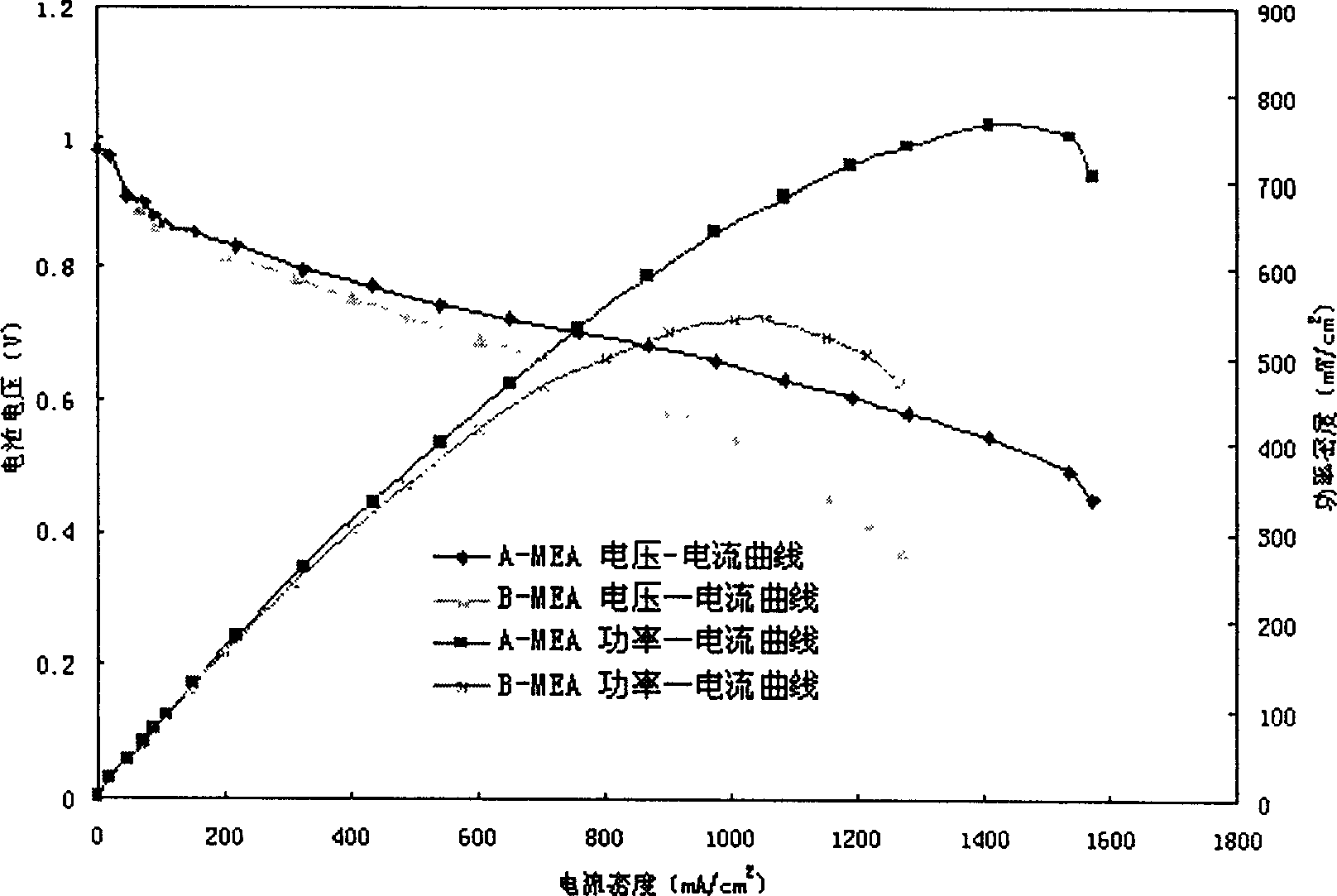
[0037] The specific operating parameters for fuel cell evaluation are as follows: the temperature of the constant temperature wat...


PUM


Abstract

Each component constituting electrode catalysis layer is in gradient distribution in Z direction of electrode (perpendicular to direction of catalysis layer). In macroscopy, electrode catalysis layer is in structure of multiple layers for example at least divided into two layers structure. First layer structure as partial hydrophobic catalysis layer composed of first catalytic activity metal, water repellent and conducting ionic polymer. Second layer structure as hydrophilic catalysis layer composed of second catalytic activity metal and conducting ionic polymer. Composite two layers constitute partial hydrophobic and partial hydrophilic composite electrode. Advantages of the structure of electrode are: enhancing capability of mass transfer of gas, especially when air as oxidant, meanwhile keeping enough capability of electron conduction and proton transfer; extending effective triphase interface of catalytic reaction; raising output power density.

Description

field of invention [0001] The invention relates to a fuel cell, in particular to a porous gas diffusion electrode for the fuel cell and a method for preparing the electrode. Background technique [0002] A fuel cell is a device that directly converts chemical energy into electrical energy. The electrode is an important part of it and the main place for electrochemical reactions; the electrode is generally composed of a diffusion layer and a catalytic layer. [0003] The characteristics of the fuel cell greatly depend on the structure of the gas diffusion electrode, especially the structure of the catalytic layer; since the electrochemical reaction is carried out on the three-phase interface on the surface of the electrocatalyst, the reaction point has the electrocatalyst, electrolyte and hydrogen or oxygen, and the electrocatalyst The three-phase interface of the chemical reaction is confined at the two-dimensional boundary of the electrocatalyst and the electrolyte, reducin...

Claims


Application Information

Patent Timeline
Patent Type & Authority Patents(China)
IPC IPC(8): H01M4/86H01M4/90H01M4/88
CPCY02E60/50
Inventor 张华民董明全邱艳玲唐倩衣宝廉刘波汪霞
Owner SUNRISE POWER CO LTD
Why Eureka
Try Eureka