Manufacture of tubular targets

A manufacturing method and tube target technology, applied in the direction of manufacturing tools, casting workshops, casting equipment, etc., can solve problems affecting stoichiometric adjustment, difficulties, etc.

Inactive Publication Date: 2002-08-14
MATERION ADVANCED MATERIALS GERMANY GMBH
View PDF5 Cites 23 Cited by
  • Summary
  • Abstract
  • Description
  • Claims
  • Application Information

AI Technical Summary

Problems solved by technology

Dissolved oxygen affects the internal structure and creates...

Method used


Image

  • Manufacture of tubular targets
  • Manufacture of tubular targets
  • Manufacture of tubular targets

Examples


example 1

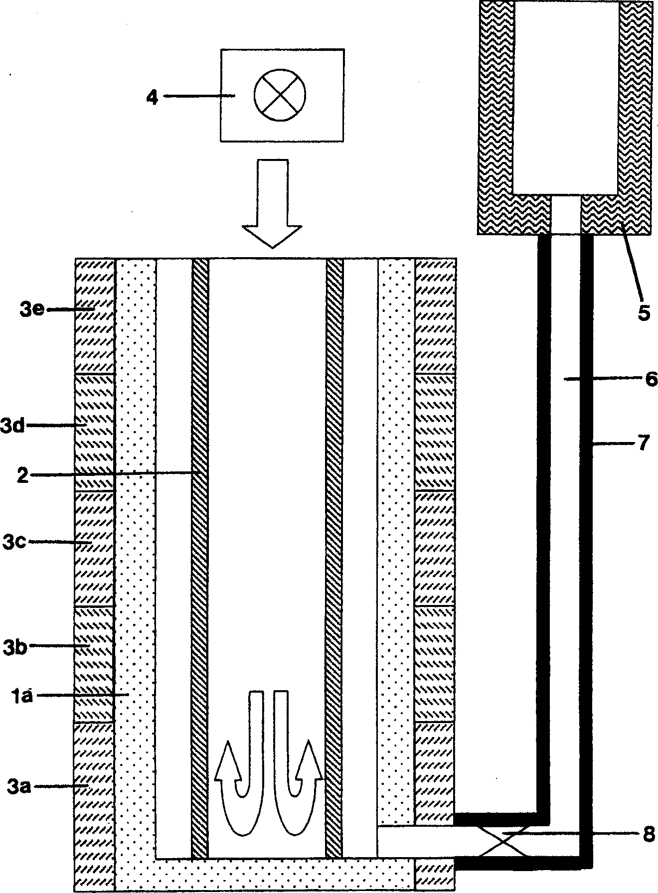
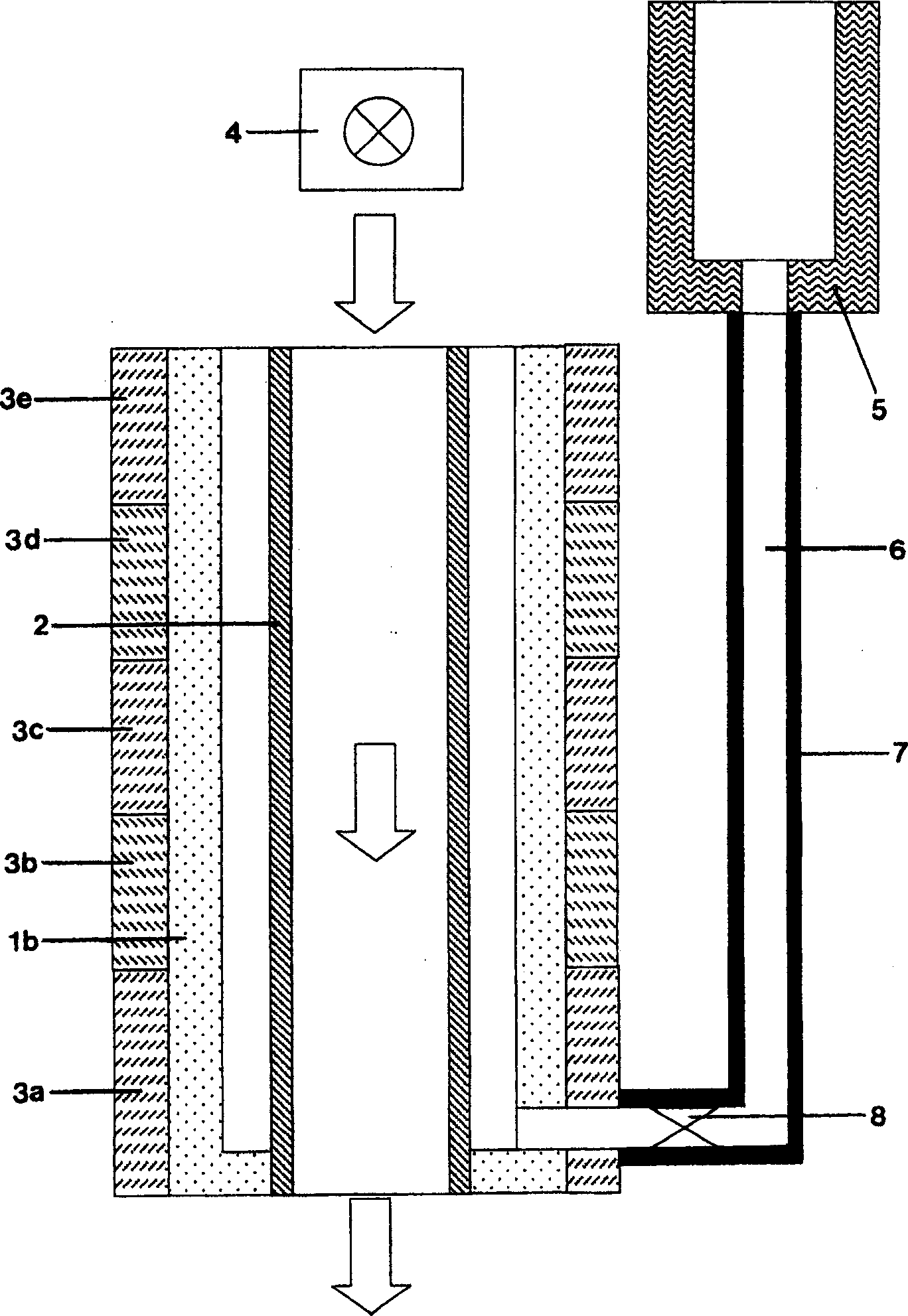
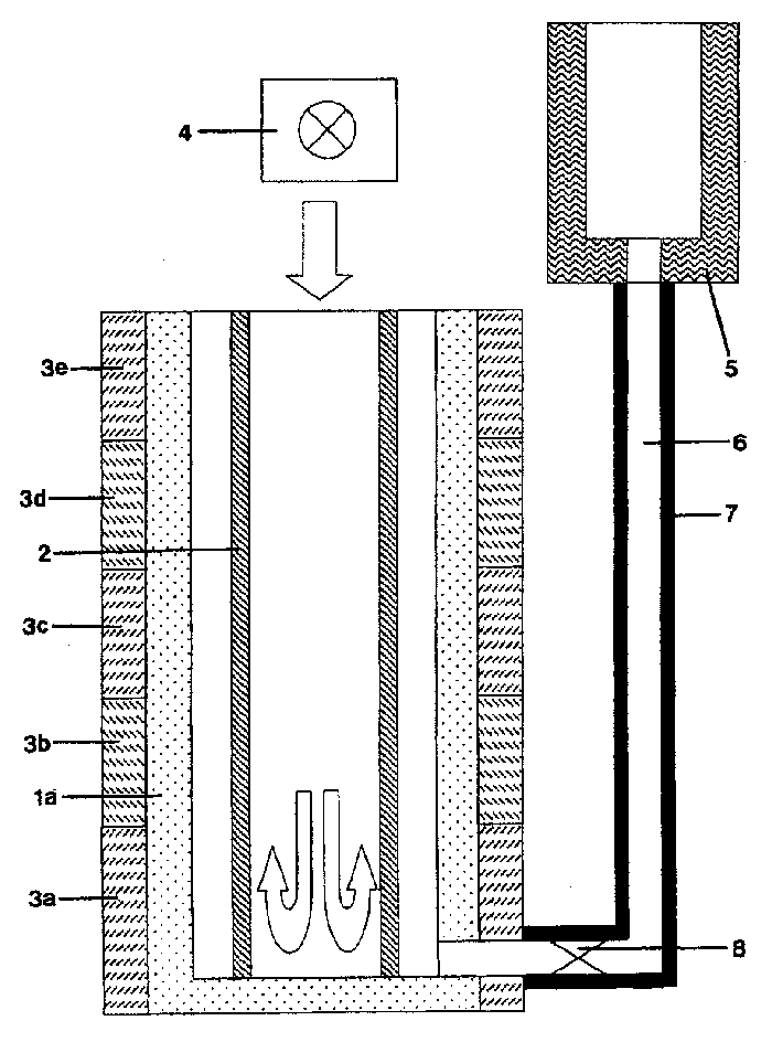
[0034] An inner tube (inner diameter 127 mm, outer diameter 133 mm, length 1500 mm) made of high-quality steel was welded to its outer diameter with a commercially available flux with tin. The welded inner tube is placed in the center of the mold halves. The casting mold is heated from the outside to approximately 300° C. by heating mats, and the inner tube is likewise heated to approximately 300° C. on its inner diameter by means of a hot air blower. In a through a siphon (see figure 1 ) in the melting crucible communicated with the casting mold with the protection of argon atmosphere to melt the tin with a purity of 99.99%. The molten tin flows into the mold through a heated pipe and fills the cavity between the inner tube and the mold until it reaches the upper edge of the mold. Then stop the hot air blower and stop heating and remove the heating pads that are arranged sequentially from the bottom of the mold. At the upper end of the mold, the metal liquid level is preve...

example 2

[0037]An inner tube (inner diameter 127 mm, outer diameter 133 mm, length 1500 mm) made of high-quality steel was welded to its outer diameter with a commercially available flux with zinc. The welded inner tube is placed in the center of the mold halves. The casting mold is heated from the outside to 500° C. by heating mats, and the inner tube is likewise heated to approximately 500° C. on its inner diameter by means of a hot air blower. In a through a siphon (see figure 1 ) protect and melt zinc with an argon atmosphere in a melting crucible communicated with the mold. Molten zinc flows into the mold through a heated pipe and fills the cavity between the inner tube and the mold until it reaches the upper edge of the mold. Then stop the hot inner blower and stop the heating and remove the heating pads arranged sequentially from the bottom of the mold. At the upper end of the mold, the molten zinc is replenished to prevent the metal liquid level from falling. After the zinc...


PUM


Abstract

A process for producing a tube target for cathode sputtering plants, in which the tube target is formed from a metallic inner tube made of a first material with a first melting point of Ts1>=900 K and a metallic outer tube that concentrically surrounds the inner tube and that is made of a second material with a second melting point of Ts2<=800 K. The inside diameter of the outer tube and the outside diameter of the inner tube are proportioned in such a way that the two tubes fit together tightly and are mechanically firmly joined. The outer tube is formed by casting the second material in a molten state in a heated, vertical, A cylindrical permanent mold, which has a heated mandrel that constitutes the inner tube. After a space between the mold and the inner tube has been filled with the molten second material, a first thermal gradient develops between the inner tube and the mold, a second thermal gradient develops between the bottom and the top of the mold, and the outer tube is simultaneously cooled from the inside to the outside and from the bottom to the top.

Description

field of invention [0001] The invention relates to a method of manufacturing a tube target for a cathode sputtering device. The tube target consists of a metal inner tube and a metal outer tube concentrically surrounding the inner tube. Wherein the inner tube has a first melting point T S1 ≥900K of the first material, while the outer tube is used with a second melting point T S2 ≤800K of the second material, and the inner diameter of the outer tube is mechanically fixedly connected to the inner diameter of the inner tube in a form-fitting manner. Furthermore, the invention relates to the use of this method. technical background [0002] The use of tube targets or rotating targets for the production of thin layers is increasingly preferred over planar targets, since tube targets achieve a higher material utilization during the deposition process (also called sputtering process). Tube targets are particularly advantageous for producing thin oxide layers by reactive sputter...

Claims


Application Information

Patent Timeline
IPC IPC(8): B22D19/16C23C14/34
CPCC23C14/3414B22D19/16B22D9/006B22D27/04
Inventor R·赫克R·于特纳D·卢普顿E·迈尔P·麦恩茨H·曼哈德特B·施滕格H·青格
Owner MATERION ADVANCED MATERIALS GERMANY GMBH
Why Eureka
Try Eureka