

Variable-gain amplifier
A gain amplifier and variable technology, applied to amplifiers with field effect devices, amplifiers with only semiconductor devices, etc., can solve the problems of small control voltage range, small maximum gain, non-linear relationship, etc., to achieve large dynamic range, The effect of high frequency and low noise
- Summary
- Abstract
- Description
- Claims
- Application Information
AI Technical Summary
Problems solved by technology
Method used
Image

Examples
Embodiment Construction
[0025] A kind of variable gain amplifier that the present invention proposes is described in detail as follows in conjunction with accompanying drawing and embodiment:
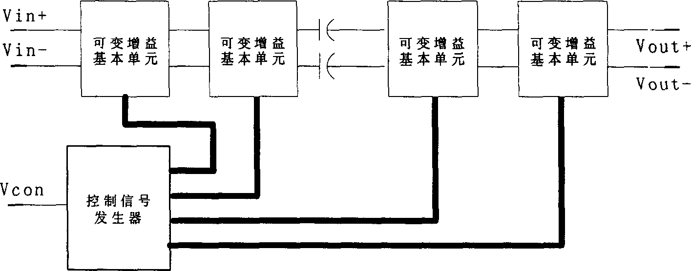
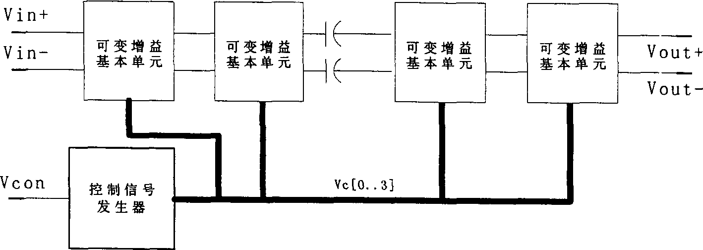
[0026] Embodiments of the variable gain amplifier circuit structure implemented by the CMOS process proposed by the present invention image 3 shown. The external input signals are differentially input RF signals Vin+ and Vin-, a DC control voltage signal Vcon and a power supply signal Vdd. It includes: three identical cascaded variable gain basic units and two parts of a control voltage generator. The control voltages Vc0, Vc1, Vc2 and Vc3 generated by the control voltage generator are output to the respective variable gain basic units. The specific circuit structure and connection relationship of each part are described in detail as follows:
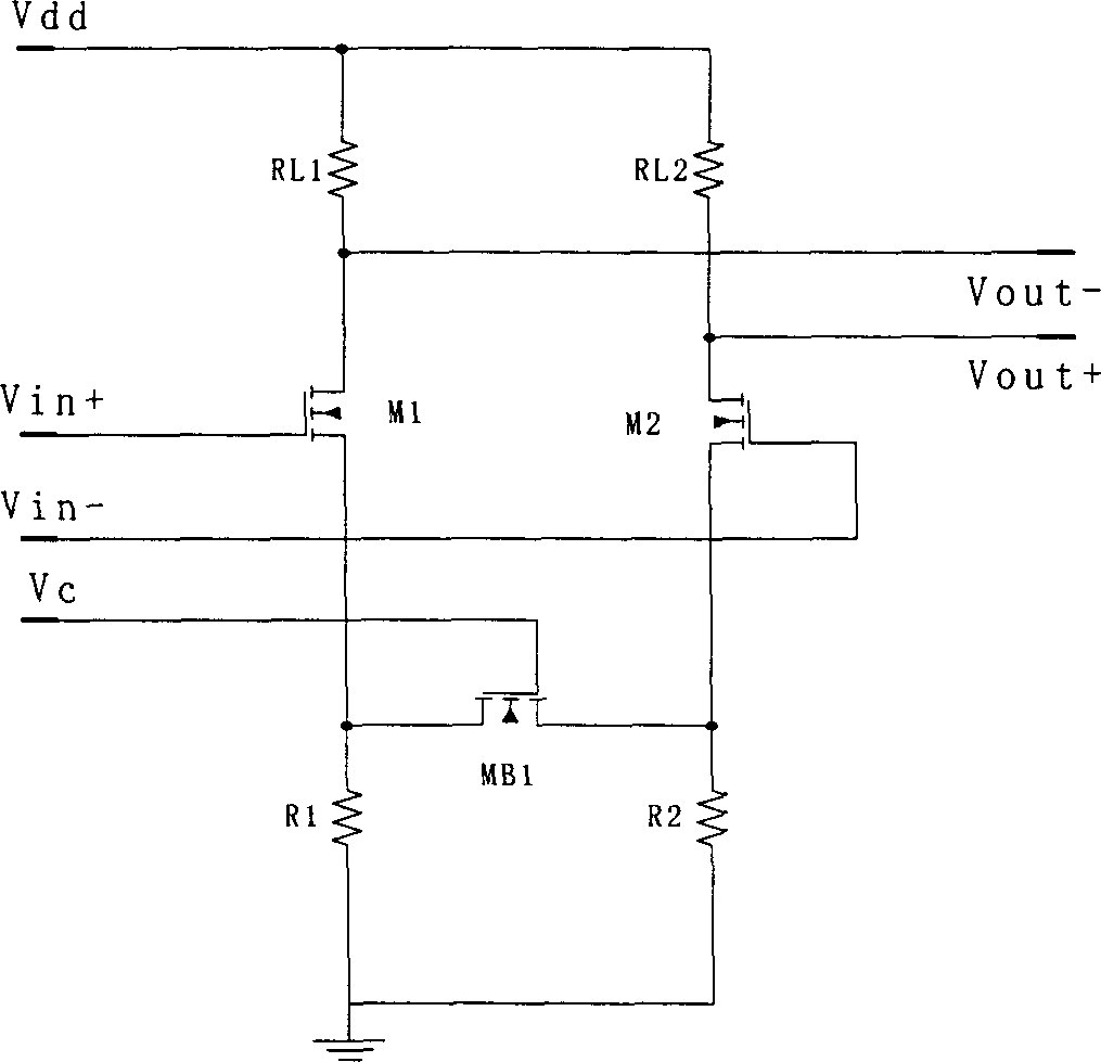
[0027] The structure of the variable gain basic unit embodiment of the present invention is as follows: Figure 4 As shown, it includes four groups of degenerate M...
PUM
 Abstract
Description
Claims
Application Information