

Catalytic conversion process of preparing ethylene and propylene
A catalytic conversion method and propylene technology, which are applied in directions such as naphtha catalytic reforming, can solve problems such as the production limit of light petroleum hydrocarbons, and achieve the effects of reducing excessive thermal cracking reaction, reducing energy consumption, and improving selectivity
- Summary
- Abstract
- Description
- Claims
- Application Information
AI Technical Summary
Problems solved by technology
Method used
Image

Examples
Embodiment 1
[0029] This example illustrates: the experimental results obtained by implementing the method provided by the present invention using a medium-sized variable-diameter riser reactor.
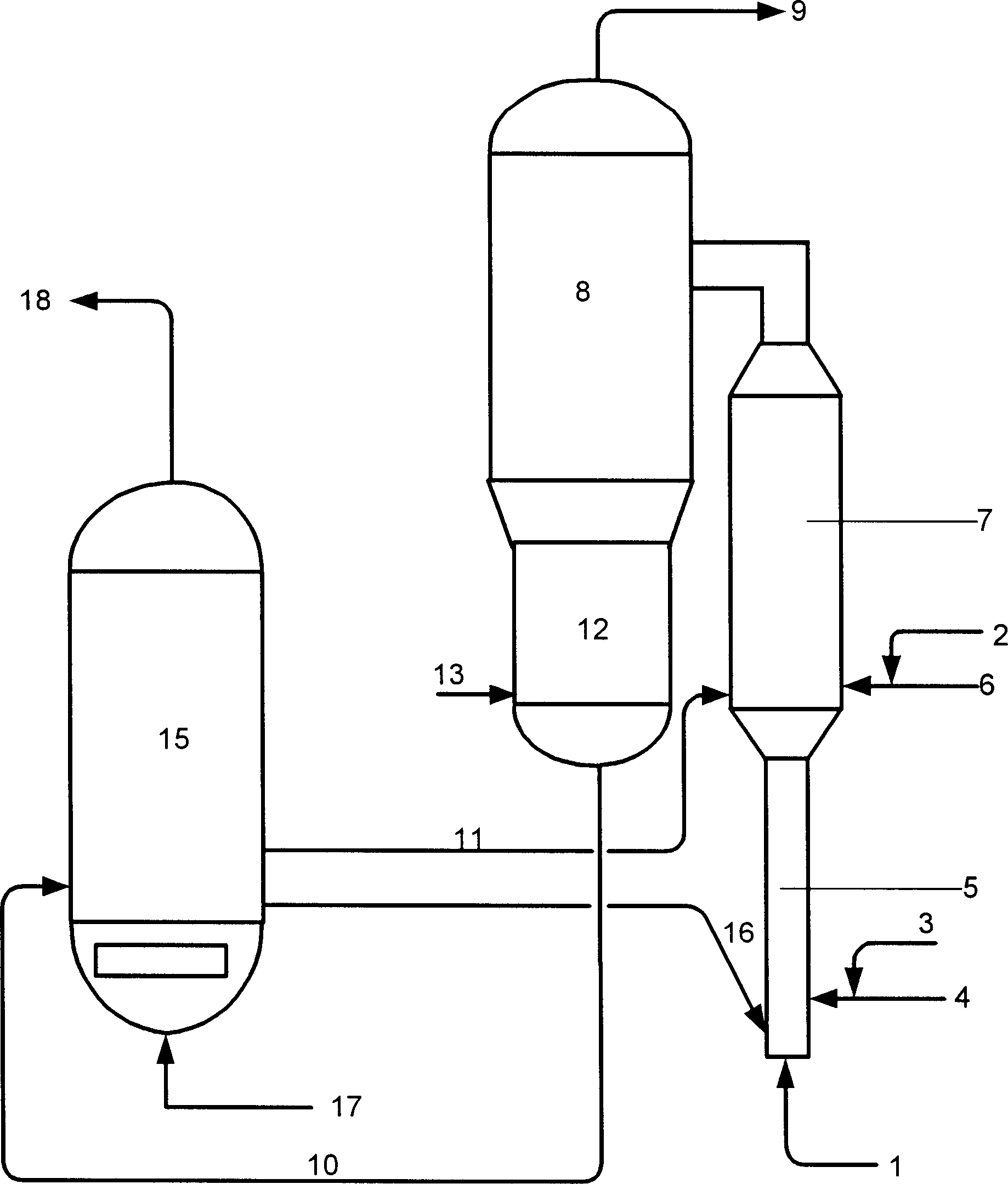
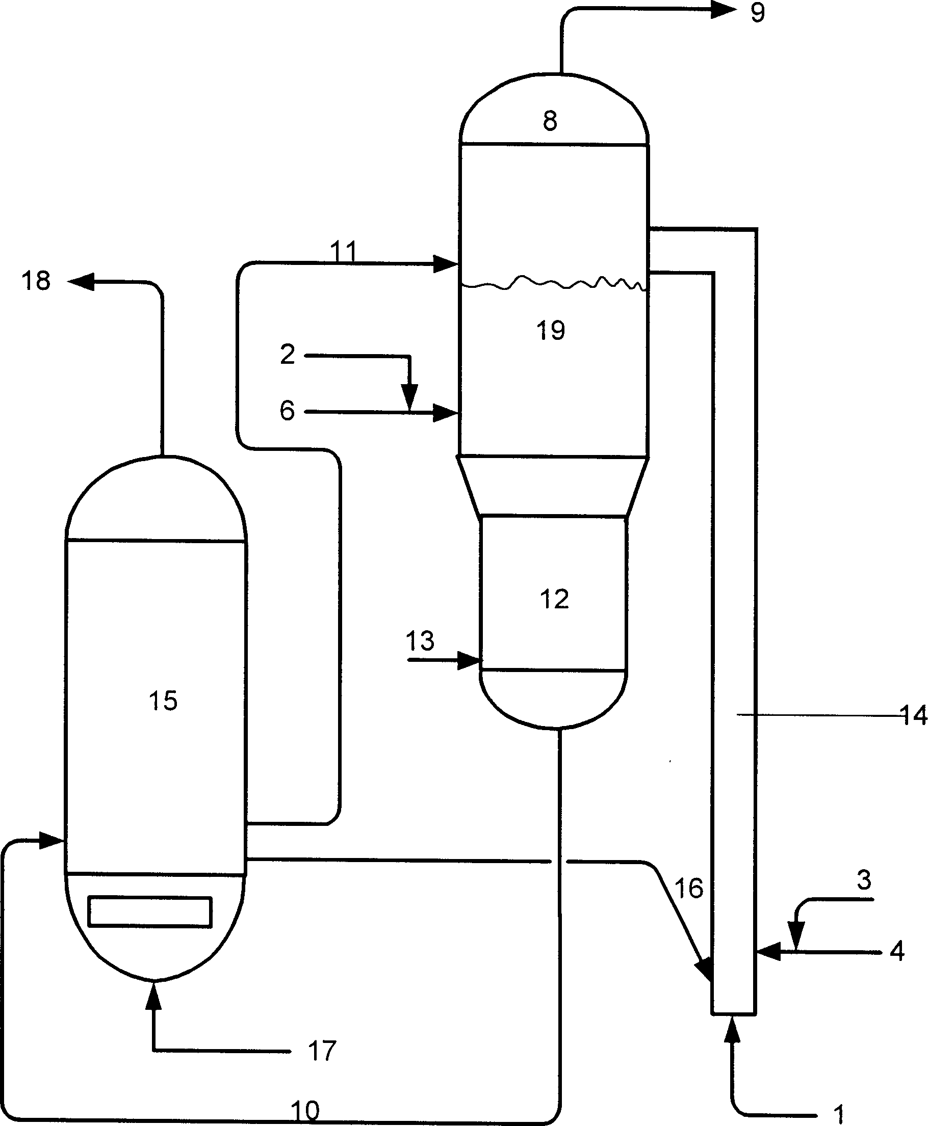
[0030] The total height of the medium-sized variable diameter riser reactor used in the test is 15 meters, the diameter of its dilute phase reaction zone is 0.025 meters, and its height is 4.5 meters; the diameter of its dense phase reaction zone is 0.1 meters, and its height is 9.0 meters. The structure of the reactor is referred to CN1237477A.
[0031] The feed oil ① in Table 1 and the four catalysts in Table 2 were used to test respectively. The main test steps are as follows: figure 1 As shown, the hot regenerated catalyst enters the bottom of the variable-diameter riser reactor through the regenerated inclined pipe 16, and is accelerated to flow upward under the action of the pre-lift medium injected from the pipeline 1. The preheated 50% by weight raw oil ① is mixed with the atomized stea...
Embodiment 2
[0034] This embodiment illustrates: the test results obtained by using the method provided by the present invention with hydrocarbon oils of different properties as raw materials.
[0035] The medium-sized variable-diameter riser reactor used in the test is the same as that in Example 1. Catalyst A listed in Table 2 was adopted, and four kinds of hydrocarbon oils in Table 1 were used as raw materials for testing, and the main test steps were the same as in Example 1.
[0036] The operating conditions and product distribution of the tests are listed in Table 4. It can be seen from Table 4 that the difference in the properties of hydrocarbon oil raw materials has a greater impact on the yield of low-carbon olefins, and the yield of ethylene varies greatly, ranging from 10.46 to 16.05% by weight; the yield of propylene is next, ranging from 15.36 to 20.76 % by weight; the yield of butene varies little, ranging from 9.26 to 11.21% by weight.
Embodiment 3
[0038] This embodiment illustrates: the influence of different operating conditions on the implementation effect of the method provided by the present invention.
[0039] The medium-sized variable-diameter riser reactor used in the test is the same as that in Example 1. Catalyst A listed in Table 2 and feed oil 1. in Table 1 were used to test, and the main test steps were the same as in Example 1.
[0040] The operating conditions and product distribution for the tests are listed in Table 5. As can be seen from Table 5, different operating conditions have different influences on the yield of low-carbon olefins. The yield of ethylene is 12.05 to 18.21% by weight; the yield of propylene is 21.10 to 23.40% by weight; butene yield is 9.36% by weight. ~13.21% by weight.
PUM
 Abstract
Description
Claims
Application Information