High frequency power amplifer, module of high frequency power amplifer and mobile telephone

A technology for power amplifiers and portable phones, used in high-frequency amplifiers, power amplifiers, improving amplifiers to improve efficiency, etc., and can solve the problem that power loss cannot be ignored.

Inactive Publication Date: 2003-04-02
RENESAS ELECTRONICS CORP
View PDF0 Cites 1 Cited by
  • Summary
  • Abstract
  • Description
  • Claims
  • Application Information

AI Technical Summary

Problems solved by technology

[0008] According to the conventional technique described above, when the high efficiency of the high-frequency power amplifier is to be further improved, the power loss caused in the switch circuits SW1 to SW3 connected in series with the signal lines cannot be ignored

Method used


Image

  • High frequency power amplifer, module of high frequency power amplifer and mobile telephone
  • High frequency power amplifer, module of high frequency power amplifer and mobile telephone
  • High frequency power amplifer, module of high frequency power amplifer and mobile telephone

Examples


Embodiment 1

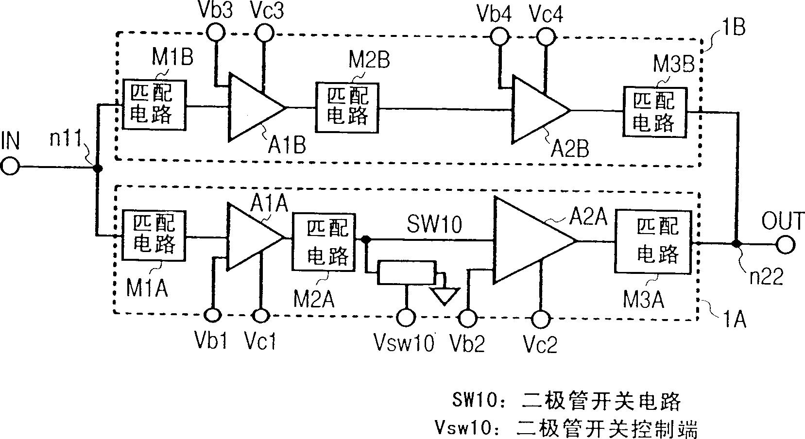
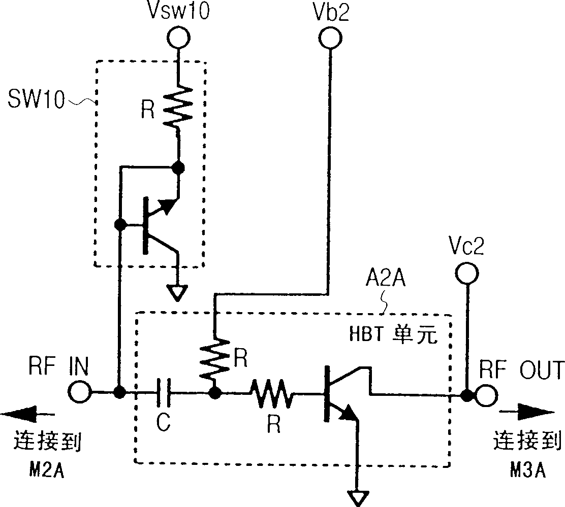
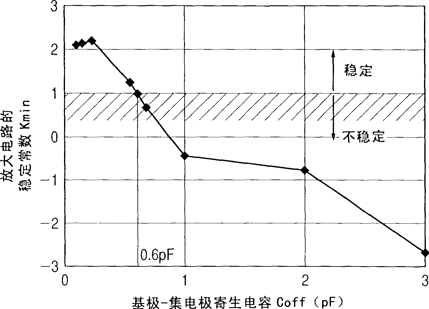
[0032] The following will refer to Figure 1 to Figure 6 A description is given of a first embodiment of the present invention. figure 1 is a structural diagram of a high-frequency power amplifier, figure 2 The circuit diagram for the basic part, image 3 , 4 and 6 are graphs used to illustrate the operation of the present invention, and Figure 5 It is a graph showing the effects of the present invention.

[0033] exist figure 1 In, reference numeral 1A denotes an amplifying circuit on the high output side, and reference numeral 1B denotes an amplifying circuit on the low output side, the input lines of the amplifying circuit 1A and the amplifying circuit 1B are connected to each other at a node n11, and the output lines thereof are connected at a node n22 connected to each other. The high output side amplifying circuit 1A passes through the series connection of the input matching circuit M1A, the primary amplifying transistor A1A, the intermediate stage matching cir...

Embodiment 2

[0053] Refer below Figure 7 to Figure 11 A second embodiment is described. According to Embodiment 2, where Embodiment 1 described above is used as a basic structure, it is constituted by a heterojunction bipolar transistor circuit to specifically constitute a high-frequency power amplifier for a W-CDMA portable telephone. Figure 7 It is the general circuit diagram of the high frequency power amplifier module. Figures 8 and 9 are for the Figure 7 The detailed circuit diagram of the part of the high frequency power amplifier, Figure 10 is a layout diagram when the circuit shown in FIG. 8 is specifically formed on one semiconductor pellet. Figure 11 is a table for explaining the method of controlling the operation of the high-frequency power amplifier, and Figure 12 and 13 It is a block diagram of a mobile phone using a high-frequency power amplifier.

[0054] exist Figure 7 In , reference numerals P1 and P2 denote semiconductor chip devices including gallium arsen...


PUM


Abstract

To provide a small-sized high frequency power amplifier for preventing oscillation by a small number of switching circuits and outputting high power and low power with high efficiencies, a high frequency power amplifier module and a portable telephone, the high frequency power amplifier is constituted by an amplifying circuit A and an amplifying circuit B connected in parallel, a size of a transistor at an output stage of the amplifying circuit B is made to be equal to or smaller than ¼ of a size of a transistor of an output stage of the amplifying circuit A and a switching circuit is connected between a signal line forward from the output stage of the amplifying circuit A and a ground terminal.

Description

technical field [0001] The present invention relates to a power amplifier for amplifying high-frequency signals from UHF (Very High Frequency) to microwave bands, and more particularly to a high-frequency power amplifier applicable to a transmitting section of a portable phone. Background technique [0002] Portable phones according to mobile communications have been remarkably advanced in their functions and structures as well as in cost reduction, and their demand has rapidly increased. In addition, according to a transistor high-frequency power amplifier used in a transmitting section of a cellular phone, in this case, small size, high efficiency, and low cost are required. First, since a high-frequency power amplifier is a device that consumes the most power in a cellular phone, the efficiency (power increase efficiency) that is the ratio of output power to power consumption constitutes a factor for extending the continuous transmission time of the cellular phone, that i...

Claims


Application Information

Patent Timeline
Patent Type & Authority Applications(China)
IPC IPC(8): H03F1/02H03F1/30H03F3/24H03F3/60H03F3/72H04B1/04
CPCH03F3/195H03F1/0277H03F2203/7221H03F2200/429H03F2203/7206H03F2200/387H03F3/72H03F1/302H03F2200/411H03F2203/7231H03F2200/555H03F2203/7236H03F2200/318H03F1/56H03F2200/111H03F3/602H03F2200/222H03F2203/7215H03F3/245
Inventor 加贺谷修大西正已关根健治田上知纪
Owner RENESAS ELECTRONICS CORP
Why Eureka
Try Eureka