
Hydraulic needle plate and its manufacture process

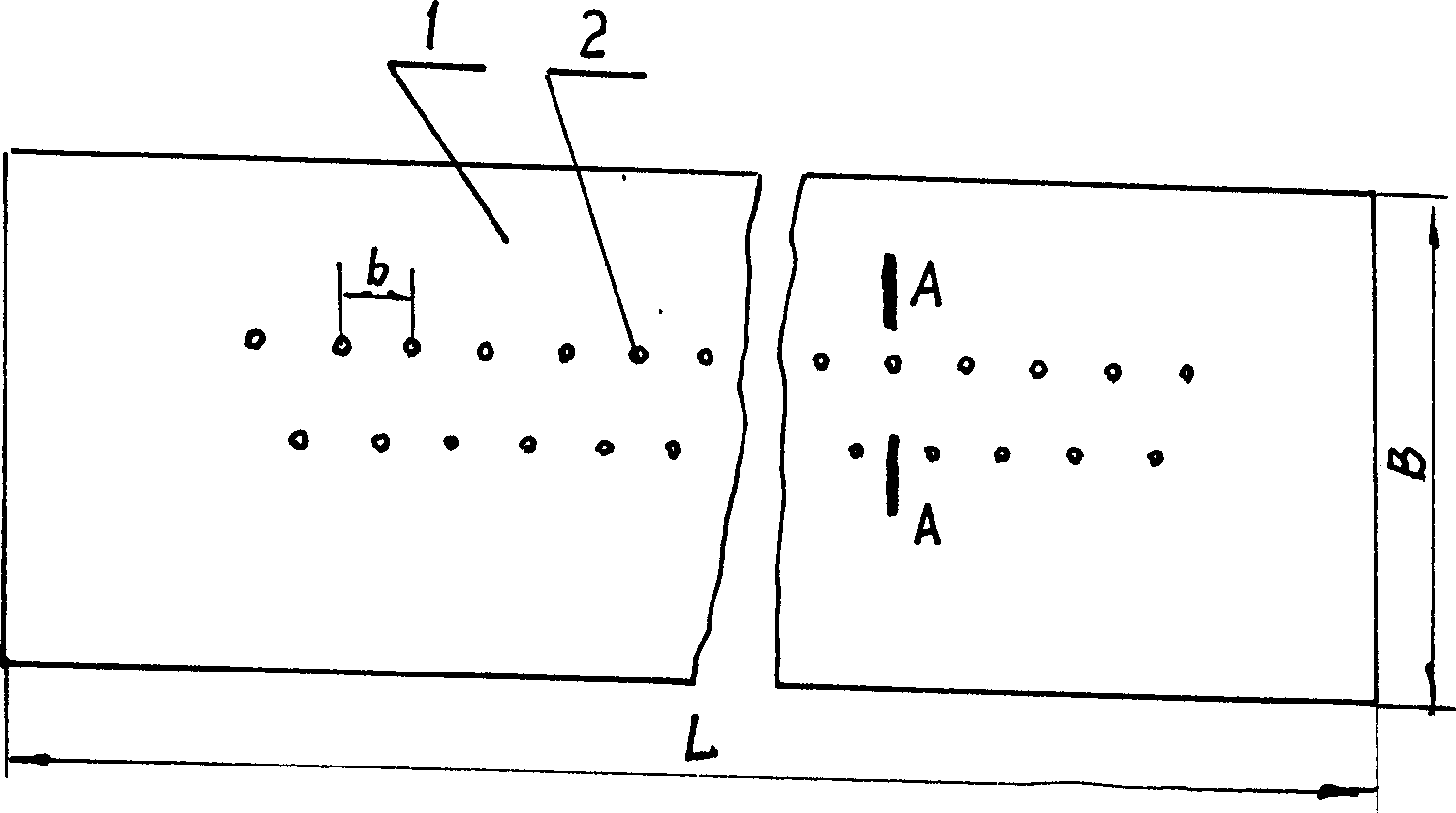
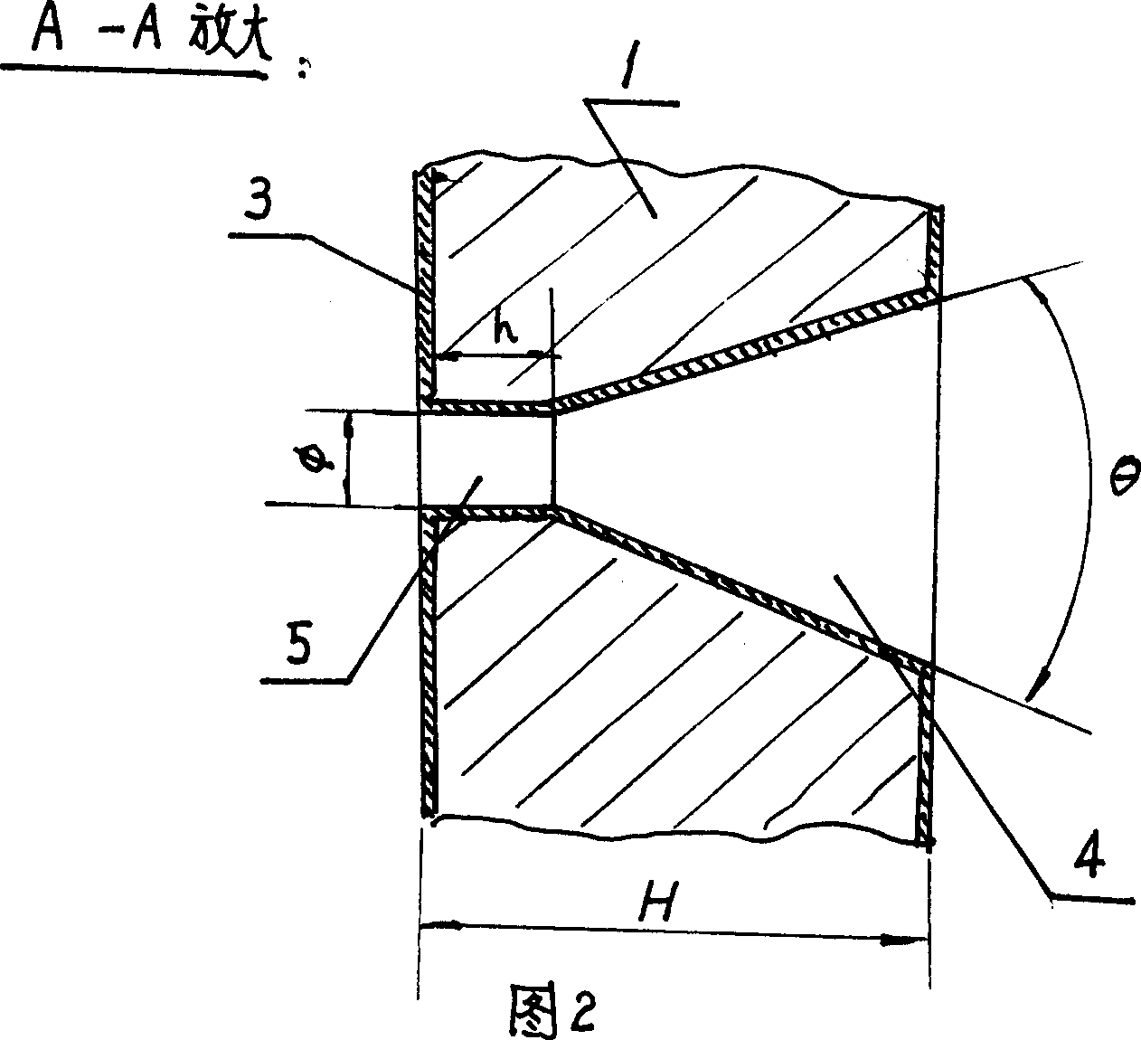
A manufacturing process, the technology of the water jet plate, which is used in acupuncture machines, non-woven fabrics, textiles and papermaking, etc., can solve the problems of the failure of the water jet plate, the deformation of the small holes of the water jet, and the impact on the service life. The effect of manufacturing and processing costs, slowing down abrasion and scratching, and prolonging service life

Inactive Publication Date: 2004-01-21
金学民
View PDF0 Cites 5 Cited by
  • Summary
  • Abstract
  • Description
  • Claims
  • Application Information

AI Technical Summary

Problems solved by technology

The hardness of the material is about HV200, which is relatively low. During use, the water spray holes of the jet plate are easily scratched by abrasion, resulting in large deformation of the water spray holes, which eventually leads to early failure of the jet plate and affects its service life.
In addition, during the manufacturing process of the stainless steel jet plate, the following processing failures often occur: because of the high deformation resistance of the material, when punching the conical dimple of the conical reaming section, the tip of the punch often breaks in the dimple , it is necessary to dig out the broken tip of the punch from the pit, and grind the raised part on the back of the plate due to stamping, which is time-consuming and labor-intensive, and increases the manufacturing cost

Method used


Image

  • Hydraulic needle plate and its manufacture process
  • Hydraulic needle plate and its manufacture process
  • Hydraulic needle plate and its manufacture process

Examples


Embodiment 1

[0021] In Example 1, Example 4 and Example 11, after the above-mentioned process steps (1)-(4), the surface plating is carried out. Wherein embodiment 1 is a chromium coating, embodiment 4 is a nickel-phosphorus coating, and the phosphorus weight percentage in the coating composition is 4~15%, and embodiment 11 is a nickel alloy coating.

[0022] Compared with the prior art, the hardness of all the above-mentioned embodiments is greatly improved, and the service life is prolonged.

[0023] Table I:

[0024]


PUM

PropertyMeasurementUnit
hardnessaaaaaaaaaa
widthaaaaaaaaaa
hardnessaaaaaaaaaa

Abstract

The present invention is hydraulic needle plate and its manufacture process. The hydraulic needle plate is manufactured with bronze and through machining and ageing treatment, or with pure titanium and through machining and surface nitridation treatment. The hydraulic needle plate has high surface hardness, long service life, good machining performance and low manufacture cost.

Description

Technical field: [0001] The invention relates to a needle plate for non-woven fabric manufacturing equipment and a manufacturing process thereof. Background technique: [0002] The non-woven fabric manufacturing equipment uses a densely covered and powerful water-spraying water needle plate. During use, it is often necessary to replace a new water-jet plate due to water spray erosion. The existing water jet plate is a long thin strip plate with a length of 1 to 10 meters, a width of about 25.4 millimeters, and a thickness of 0.3 to 1.8 millimeters, on which one or more rows of small water spray holes are evenly distributed. Two adjacent rows of small water spray holes are arranged in a misplaced position with a distance of 0.4 to 1.6 mm. The small water spray holes are centrally perforated and the upper end has a tapered reaming section with a taper of 30° to 90°. The diameter of the central perforated hole is Φ0. 10-0.13 mm, the depth of the central perforation is 0.2-0.5 ...

Claims


Application Information

Patent Timeline
Patent Type & Authority Applications(China)
IPC IPC(8): C22C9/00D04H18/04
Inventor 金学民
Owner 金学民
Learn More