
Method and system for observing all signals inside programmable digital IC chip
A technology for integrated circuits and test systems, which is applied in the field of testing and verification of programmable digital integrated circuit chips, and can solve problems such as short waveform length, errors, and inability to be used in ASICs.
- Summary
- Abstract
- Description
- Claims
- Application Information
AI Technical Summary
Problems solved by technology
Method used
Image

Examples
Embodiment Construction
[0054] The present invention will be further described below in conjunction with the accompanying drawings and embodiments.
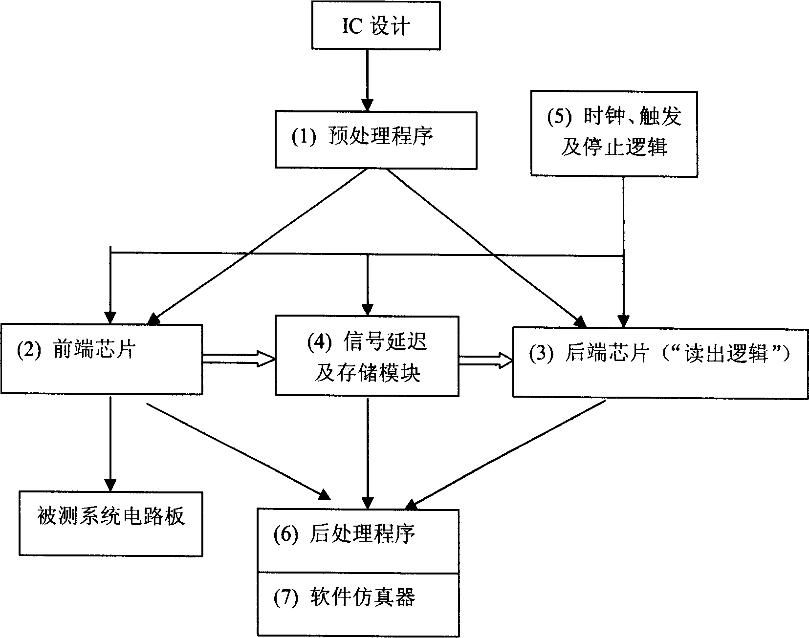
[0055] The composition of the entire test system, such as Figure 4 As shown, the host computer can be a microcomputer or a workstation, and the preprocessing program, postprocessing program, software emulator and system control program all run on the host computer. The test system composed of back-end chip, "signal, delay and storage module" and "clock, trigger and stop logic" is installed in a separate chassis, and it is connected to the microcomputer through PCI bus or USB bus. The front-end chip is installed on the circuit board under test to realize real-time and online testing. Cables are used between the front-end chip and the test system to send the signals on the pins of all the front-end chips to the chassis of the test system. In order to increase the transmission rate of cables, it is necessary to expand the number of cables and distribute...
PUM
 Abstract
Description
Claims
Application Information