
Tuneable vertical catity laser amplifier

A technology of laser amplifiers and lasers, which is applied to lasers, laser components, semiconductor lasers, etc., can solve problems such as high cost, and achieve the effects of easy implementation, reliable cost, and easy implementation

Inactive Publication Date: 2004-10-13
OPTOGONE
View PDF0 Cites 0 Cited by
  • Summary
  • Abstract
  • Description
  • Claims
  • Application Information

AI Technical Summary

Problems solved by technology

[0019] FFPSEL technology also has several disadvantages, notably high cost, cavity alignment and stability must be well controlled, and long times (on the order of 1 ms) required to change wavelength

Method used


Image

  • Tuneable vertical catity laser amplifier
  • Tuneable vertical catity laser amplifier
  • Tuneable vertical catity laser amplifier

Examples


Embodiment Construction

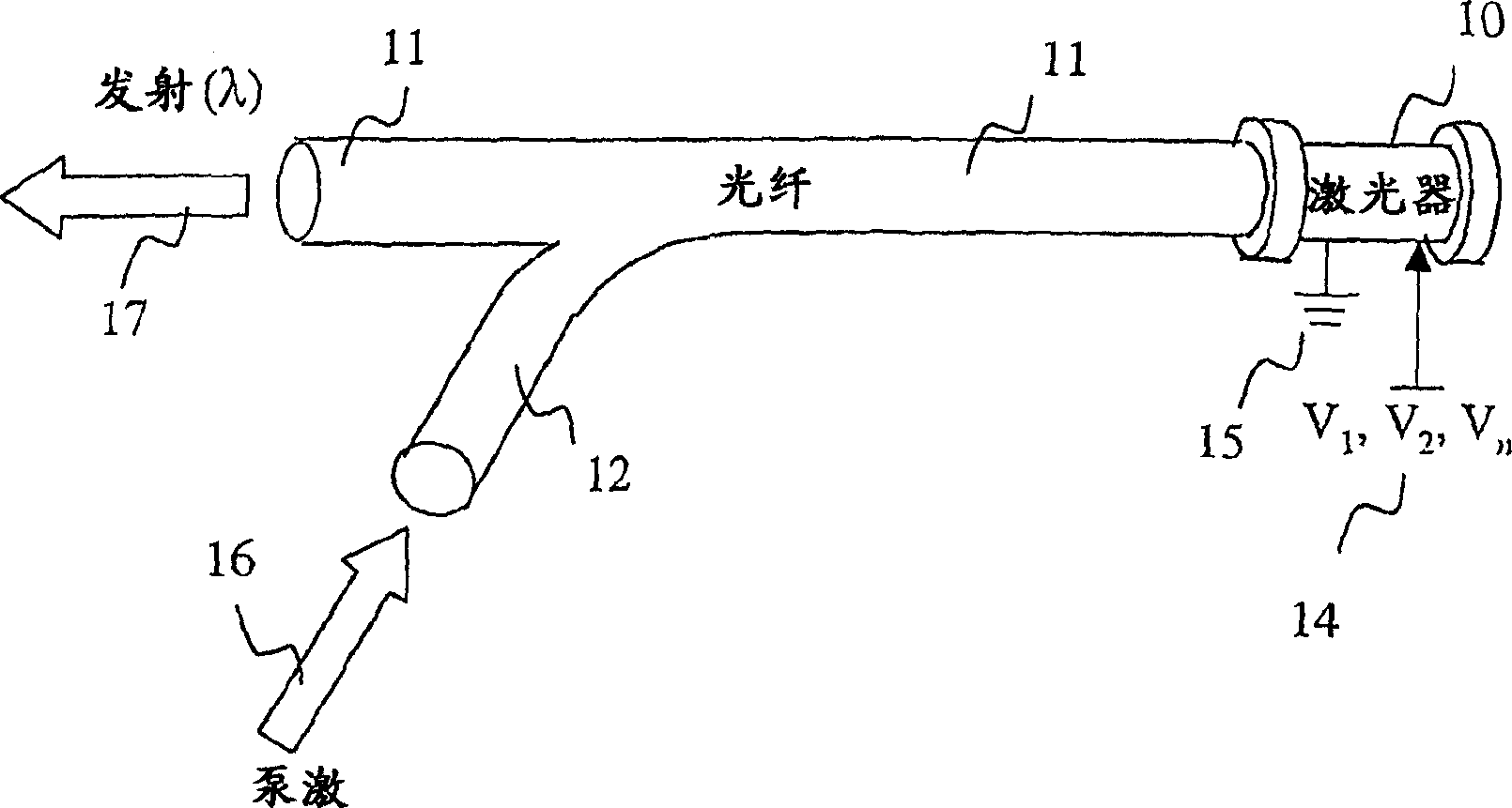
[0072] General principle of the invention

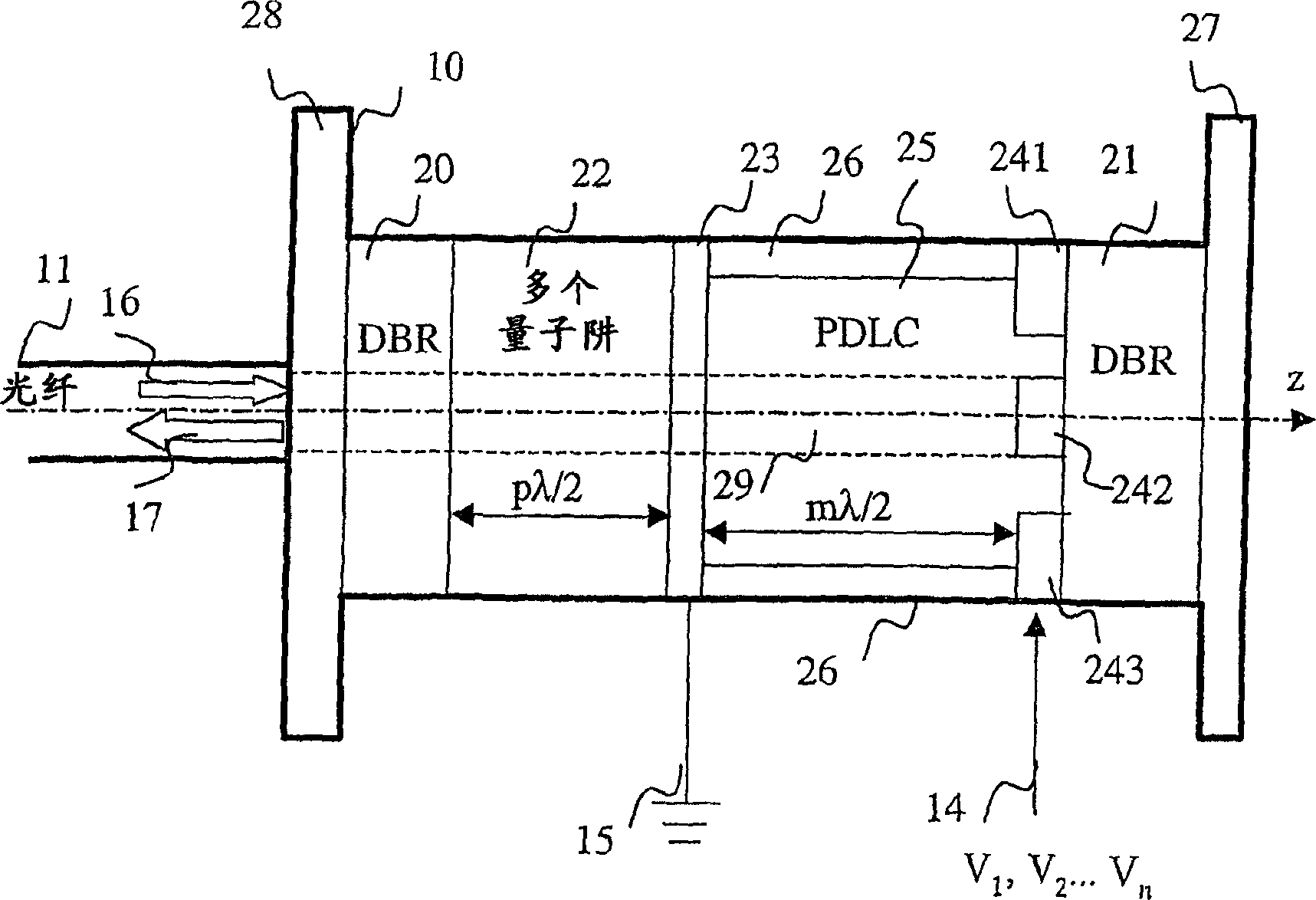
[0073] The general principle of the invention is based on the combination of:

[0074] - active elements, for example of the multiple quantum well type; and

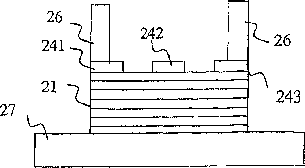
[0075] - including phase shifting regions of optoelectronic elements;

[0076] The assembly forms a cavity.

[0077] The active element and the phase shifting region are contained between two DBR mirrors in order to generate and or amplify a light beam of a given wavelength. This wavelength depends on the optical thickness of the cavity through which the beam passes (remember that optical thickness is equal to the product of physical thickness and dielectric index).

[0078] The phase shifting region is subjected to one or more electric fields, which can be acted upon by controlling the voltage of the electrodes. The index of the phase-shifting region, and thus its optical thickness, can vary depending on the voltage applied to the electrodes. The result is a low-cost, rel...


PUM


Abstract

The invention concerns a tuneable vertical cavity laser amplifier, comprising, inside the cavity (25) at least an electro-optical element designed to tune the wavelength (lambda) of the laser amplifier, at least one of the electro-optical elements including an isotropic material in a transverse plane. The invention also concerns a telecommunication system comprising the tuneable laser amplifier, an array comprising a plurality of laser amplifier and a method for making same.

Description

technical field [0001] The invention relates to the field of optical devices, in particular to optical devices for high-speed optical networks. [0002] More precisely, the invention relates to laser amplifiers with tunable wavelength. Background technique [0003] For the purposes of this specification, a laser amplifier means a laser that behaves like a laser source and / or amplifier. When the energy input to the laser is greater than the lasing threshold specified for the device, the laser generally behaves like a laser source. Under other conditions, it only acts as an amplifier. [0004] Tunable lasers can be grouped into two main categories: [0005] an edge emitting laser; and [0006] A longitudinal cavity laser. [0007] Tunable semiconductor laser amplifiers are usually obtained using edge-emitting lasers of the DBR (Distributed Bragg Reflector) type. DBR is described in detail in "Tune In!" by P. Heywood, April 2000 and is available at www.lightreading.com T...

Claims


Application Information

Patent Timeline
IPC IPC(8): G02F1/065G02F1/1334H01S3/10H01S5/06H01S5/183
CPCH01S5/18302H01S5/50H01S5/0607
Inventor 让-路易斯·德·布格雷内·德·拉·托奈伊维维昂·布鲁格
Owner OPTOGONE
Learn More