Fibre-optical raster of implementing arbitrary target response

A fiber grating and target response technology, which is used in optical fiber communication, optical sensing and other related optical signal processing fields. , to reduce the production cost, expand the scope, and expand the scope of application

Inactive Publication Date: 2005-01-05
TSINGHUA UNIV
View PDF0 Cites 25 Cited by
  • Summary
  • Abstract
  • Description
  • Claims
  • Application Information

AI Technical Summary

Problems solved by technology

[0023] The purpose of the present invention is to solve the problem that the above-mentioned fiber grating structure and phase shift technology obtained by using the reconstruction algorithm are difficult to realize with the traditional phase template-scanning method, and the traditional equivalent chirp method cannot realize any target phase response and Problems with ignoring the magnitude response of fiber gratings

Method used


Image

  • Fibre-optical raster of implementing arbitrary target response
  • Fibre-optical raster of implementing arbitrary target response
  • Fibre-optical raster of implementing arbitrary target response

Examples


Embodiment I

[0060] This embodiment can realize a fiber grating that can be used for third-order dispersion compensation.

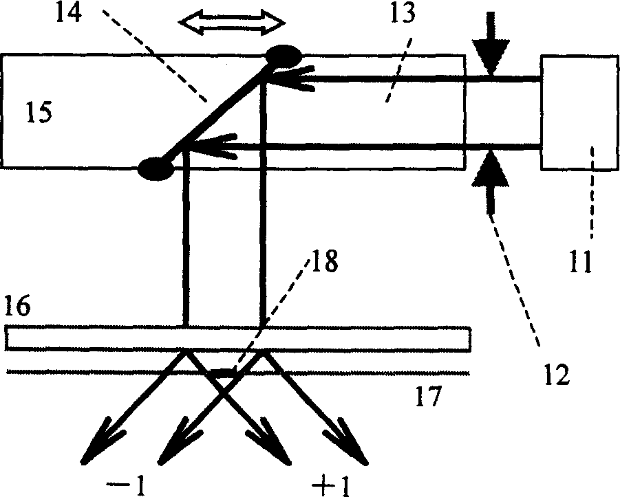
[0061] The device used in this embodiment is as figure 1 shown, where

[0062] A. The ultraviolet laser 11 adopts a continuous 244nm argon ion frequency-doubled laser, which is produced by Coherent Company of the United States.

[0063] B. The translation stage 15 is produced by PI Company in Germany, the model is MS85E, and the motion accuracy is 0.1 μm.

[0064] C. The period of the initial end of the phase template 16 used is 2Λ=1061nm, and the chirp coefficient is 2C=-0.048nm / cm.

[0065] D. The photosensitive optical fiber 17 used is the PS-RMS-50 type photosensitive optical fiber produced by Canada INO Company.
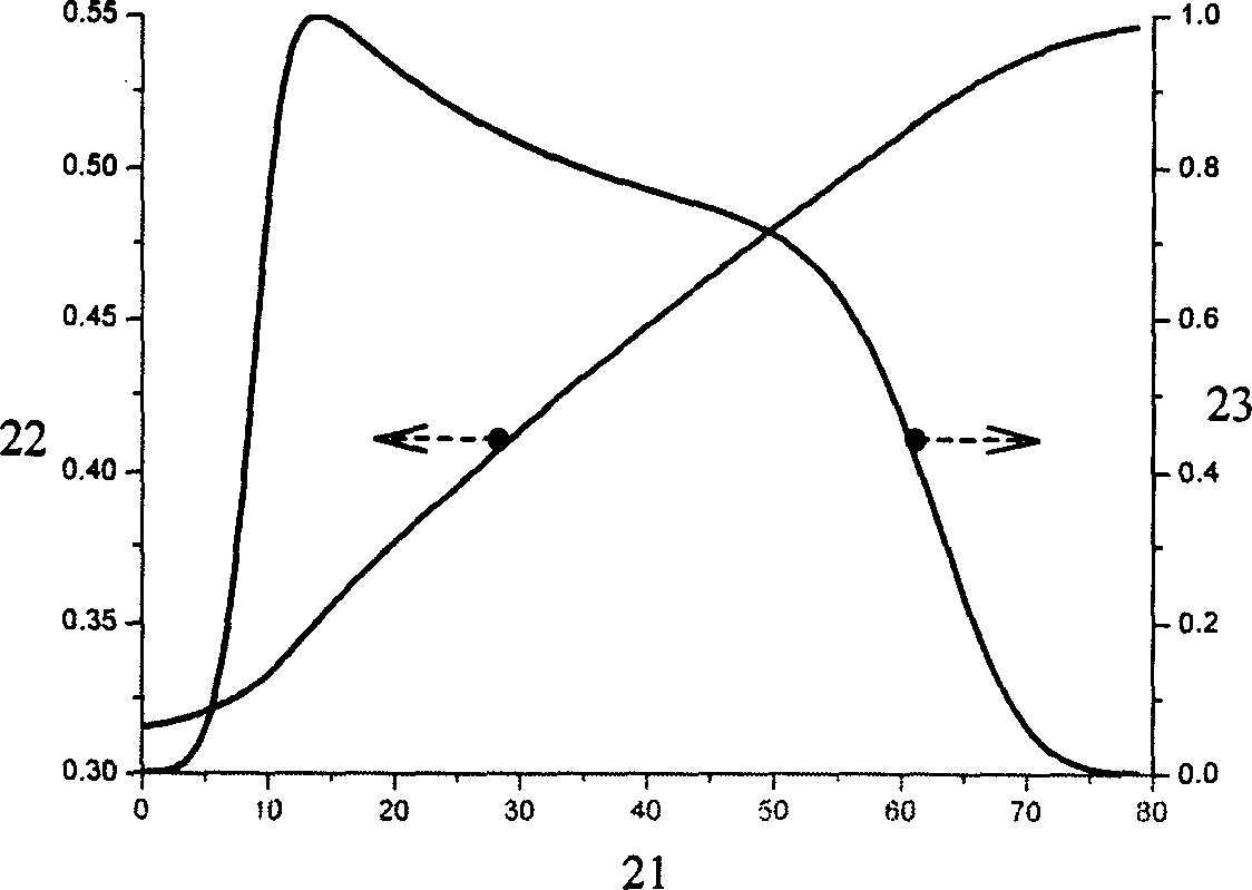
[0066] Λ of this example S 、 S (z) and A S (z) is obtained from the target reflection response; the properties of the target reflection response adopted are as follows:

[0067] A. The expression of amplitude reflectance changing with wavelength...

Embodiment II

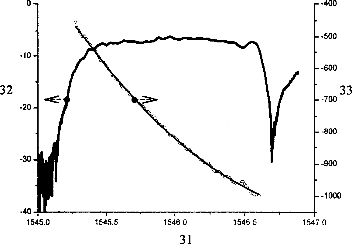
[0078] In this embodiment, reflection responses with π phase shift characteristics can be obtained in the -1 order channel of the sampled fiber grating.

[0079] This embodiment combines the invention of realizing an optical filter with an arbitrary target reflection response, that is, the exposure position z of the original sampling fiber grating in this embodiment k 0 and the introduced refractive index modulation amplitude A k 0 is obtained from formula (8), and the required Λ in formula (8) S 、 S (z) and A S (z) is a given.

[0080] The device used in this embodiment is as figure 1 shown, where

[0081] A. The ultraviolet laser 11 adopts a continuous 244nm argon ion frequency-doubled laser, which is produced by Coherent Company of the United States.

[0082] B. The translation stage 15 is produced by PI Company in Germany, the model is MS85E, and the motion accuracy is 0.1 μm.

[0083] C. The period of the initial end of the phase template 16 used is 2Λ=1061nm, a...


PUM


Abstract

The invention relates to a fiber grating which can realize any target response, which belongs to fiber communication, optical sensor and other relative light signal processing fields. The product is a fiber grating of sampling structure realized with phase model scanning method; the period and phase function of the initial end of the fiber grating, As, Phi s (z) and A s (z) are period, phase function and apodization function of any given fiber grating initial end. And it can acquires distance Zk from the K ultraviolet exposure position to the sample fiber grating initial end and the amplitude Ak of refraction rate modulation leaded in at the Zk. The character of the invention is: its reflection spectrum has multi-channel type, and some special reflection peak in them has the demanded target reflection response, or has the character of target phase shift.

Description

technical field [0001] The invention belongs to the fields of optical fiber communication, optical sensing and other related optical signal processing, and in particular relates to the structure design of optical fiber grating filter. Background of the invention [0002] Optical filters play a very important role in many fields involving optical signal processing, such as optical fiber communication and optical sensing. In optical fiber communication, the optical pulse as the information carrier will be affected by various factors and broaden when it propagates in the optical fiber, so that the receiving end cannot correctly identify the information content; the distortion of the optical pulse can be compensated by using a specific optical filter, such as Dispersion compensators can counteract the effects of dispersion in transmission fibers, polarization-mode compensators can counteract the effects of polarization-mode dispersion in propagation fibers, and so on. In the op...

Claims


Application Information

Patent Timeline
Patent Type & Authority Applications(China)
IPC IPC(8): G02B6/124
Inventor 戴一堂陈向飞夏历姜典杰谢世钟
Owner TSINGHUA UNIV
Why Eureka
Try Eureka