Carbon source denitrogenation inside cells for sewage

A carbon source nitrogen method and denitrification technology, applied in the field of environmental protection, can solve the problems of low denitrification efficiency, high infrastructure costs, and difficulty in controlling the dosage, so as to improve the denitrification efficiency, reduce the amount of excess sludge, and save all resources. The effect of energy

Inactive Publication Date: 2005-01-12
FUDAN UNIV
View PDF0 Cites 6 Cited by
  • Summary
  • Abstract
  • Description
  • Claims
  • Application Information

AI Technical Summary

Problems solved by technology

Research and engineering practice show that this method has high and stable denitrification efficiency, but it has the following defects: (1) Carbon sources need to be added to the denitrification tank, the cost of chemicals is high, and the dosage is difficult to control, which may easily cause organic matter Leakage; (2) Due to the need to add chemicals and automatic online monitoring and control, there are many equipments, high operation requirements, complicated management, and high quality requirements for operators; (3) All carbon in the influent water needs to be oxidized into CO 2 and H 2 O, the hydraulic retention time is long, the pool volume is large, the floor area is large, and the infrastructure cost is high; (4) Aeration power consumption is high
It is the anoxic denitrification tank in the front, the aerobic nitrification tank in the back, it uses the organic matter in the influent as the denitrification carbon source, overcomes the defect that the O / A method needs to add chemicals as the denitrification carbon source, but it It also inevitably has the following defects: (1) a large amount of reflux mixture is required to improve the denitrification efficiency, and the reflux ratio is usually required to be 7-8:1, so the energy consumption is large and the operating cost is high; (2) the denitrification efficiency is low; (3) The effluent contains a certain concentration of nitrates. In the secondary settling tank, denitrification may occur, causing the sludge to float up and affecting the quality of the effluent.
Although the fixed growth of microorganisms on the membrane is conducive to the growth of autotrophic nitrifying bacteria with a long generation time, nitrification only occurs under low load conditions, and there are also some defects as follows: (1) The use of fillers greatly increases the investment. (2) Nitrification can only occur under low-load operating conditions, and the pool is large in size and high in cost; (3) The denitrification efficiency is low; (4) Membrane shedding is easy to cause blockage; (5) Water distribution is not easy to be uniform; ( 6) Growth of pond flies, etc.

Method used


Image

  • Carbon source denitrogenation inside cells for sewage

Examples


Embodiment 1

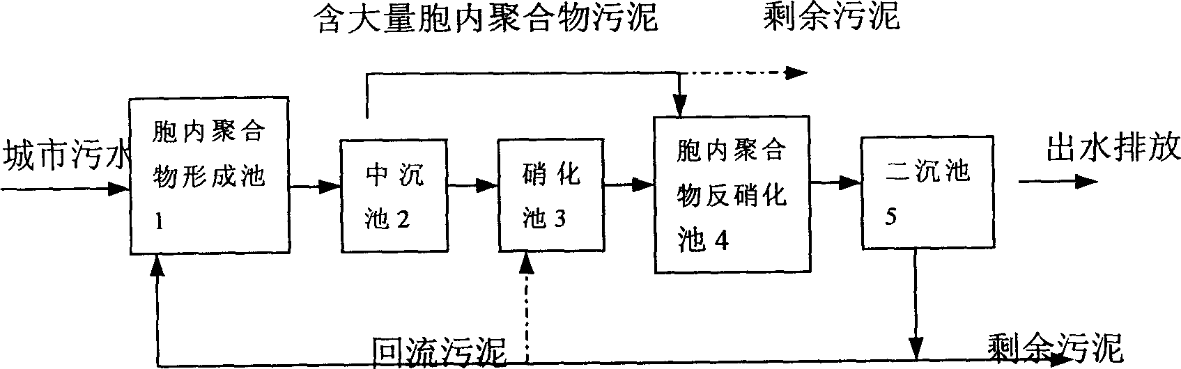
[0037] The urban sewage from a certain place is pretreated by grille, grit and primary sedimentation, and then mixed with the return sludge from the secondary sedimentation tank in the intracellular polymer formation tank. The hydraulic retention time is 40 minutes, and the dissolved oxygen is controlled. At about 2mg / l, the mixed solution from the intracellular polymer formation tank enters the intermediate sedimentation tank, and the sedimentation time is 1.5 hours. The sedimentation sludge flows into the intracellular polymer denitrification tank, and the supernatant enters the nitrification tank (using Soft fiber packed bed reactor), the hydraulic retention time is 6 hours, and the dissolved oxygen is controlled at about 3.5mg / l. The sludge phase of the inner polymer is mixed, and the hydraulic retention time is 1.0 hour, and the underwater low-speed submersible mixer is used for mixing. The mixed liquid flowing out from the intracellular polymer denitrification tank enter...

Embodiment 2

[0040] The urban sewage from a certain place is pretreated by grille, grit and primary sedimentation, and then mixed with the return sludge from the secondary sedimentation tank in the intracellular polymer formation tank. The hydraulic retention time is 30 minutes, and the dissolved oxygen is controlled. Around 2mg / l. The mixed solution from the intracellular polymer formation tank enters the intermediate sedimentation tank, and the sedimentation time is 1.5 hours. The sedimentation sludge flows into the intracellular polymer denitrification tank, and the supernatant enters the nitrification tank (soft fiber packed bed reactor) ), the effective residence time is 4.5 hours, and the dissolved oxygen is controlled at about 3mg / l. The liquid flowing out from the nitrification tank enters the intracellular polymer and the nitrification tank, and is mixed with the sludge containing a large amount of intracellular polymer from the intermediate sedimentation tank. The hydraulic reten...

Embodiment 3

[0043] The urban sewage from a certain place is pretreated by grille, grit and primary sedimentation, and mixed with the return sludge from the secondary sedimentation tank in the intracellular polymer formation tank. The hydraulic retention time is 20 minutes, and the dissolved oxygen is controlled. At about 2 mg / l, the mixed solution from the intracellular polymer formation tank enters the intermediate sedimentation tank, and the sedimentation time is 1.5 hours. The sedimentation sludge flows into the intracellular polymer denitrification tank, and the supernatant enters the nitrification tank (soft fiber packed bed reactor), the hydraulic retention time is 3 hours, and the dissolved oxygen is controlled at about 2.5mg / l. The sludge phase of the polymer is mixed, and the hydraulic retention time is 0.5 hours, and the underwater low-speed submersible mixer is used for mixing. The mixed liquid flowing out from the intracellular polymer denitrification tank enters the secondary...


PUM


Abstract

In aerobic condition, soluble organic substance in water can be absorbed by microbe in short time, the organic substance is in microbe cells mainly in way of intracellular polymer and used as anti-nitrocarbon source in anti-nitrify tank. The processing steps are: mixing reaction, solid-liquid separating, nitrify and anti-nitrifying.

Description

technical field [0001] The invention belongs to the technical field of environmental protection, and in particular relates to a method for denitrification of carbon sources in sewage cells. Background technique [0002] At the beginning of the last century, with the invention of wastewater biological treatment technology, water pollution control technology has been greatly improved. By the 1970s, the problem of black and odorous water bodies in western developed countries was basically solved, followed by nitrogen pollution. The problem of eutrophication in water bodies is becoming more and more prominent all over the world. Nitrogen is a controlling factor for eutrophication in water bodies of inland rivers and lakes. Since then, denitrification technology has become a research hotspot in the academic and engineering circles of the international environmental protection technology field, and a variety of denitrification technologies have been invented, which are mainly div...

Claims


Application Information

Patent Timeline
Patent Type & Authority Applications(China)
IPC IPC(8): C02F3/30
Inventor 刘燕徐祖信王红武李怀正屈计宁
Owner FUDAN UNIV
Why Eureka
Try Eureka