Rotor permanent magnet conversion governing dynamo and its hub electric wheel

A variable frequency speed regulating motor and rotor technology, which is applied to synchronous motors with static armatures and rotating magnets, electric components, magnetic circuit rotating parts, etc. The low utilization rate affects the efficiency of the whole vehicle and affects the layout of the whole vehicle.

Pending Publication Date: 2005-01-12
金胜虎
View PDF0 Cites 11 Cited by
  • Summary
  • Abstract
  • Description
  • Claims
  • Application Information

AI Technical Summary

Problems solved by technology

[0004] The electric drive system is the heart of the electric vehicle. The technical solutions adopted at home and abroad mainly include DC motor system, induction motor-inverter system, permanent magnet motor system and synchronous reluctance motor system. The driving form is the transmission central bridge drive, Wheel-side deceleration motor drive, rim deceleration electric wheel drive, hub electric wheel drive, etc. Among them, the main disadvantage of the central bridge drive and wheel-side deceleration motor drive system is that the reducer and the motor occupy a large space in the form of a bridge or a half bridge. Less than the ultra-low floor of the whole vehicle, the height of the whole vehicle cannot be lowered, which affects the layout of the whole vehicle; although the rim deceleration electric wheel can overcome the above shortcomings and the mechanical deceleration can bring a large torque and sufficient speed range, but it needs The developed planetary reducer, large-diameter bearings, rim docking, and large-diameter oil seals require high machining accuracy and technical content. The effective volume of the motor is relatively small, so the development is difficult.
[0005] At present, the driving motors for electric vehicles are ideally switched reluctance motors and permanent magnet brushless DC motors, but if they do not use mechanical deceleration, they cannot make full use of their rated power and rated speed. In other words, the effective power and speed of the motor The low utilization rate of the electric vehicle affects the efficiency of the whole vehicle; therefore, the existing electric motor cannot meet the requirements of the full driving of the electric vehicle

Method used


Image

  • Rotor permanent magnet conversion governing dynamo and its hub electric wheel
  • Rotor permanent magnet conversion governing dynamo and its hub electric wheel
  • Rotor permanent magnet conversion governing dynamo and its hub electric wheel

Examples


Embodiment Construction

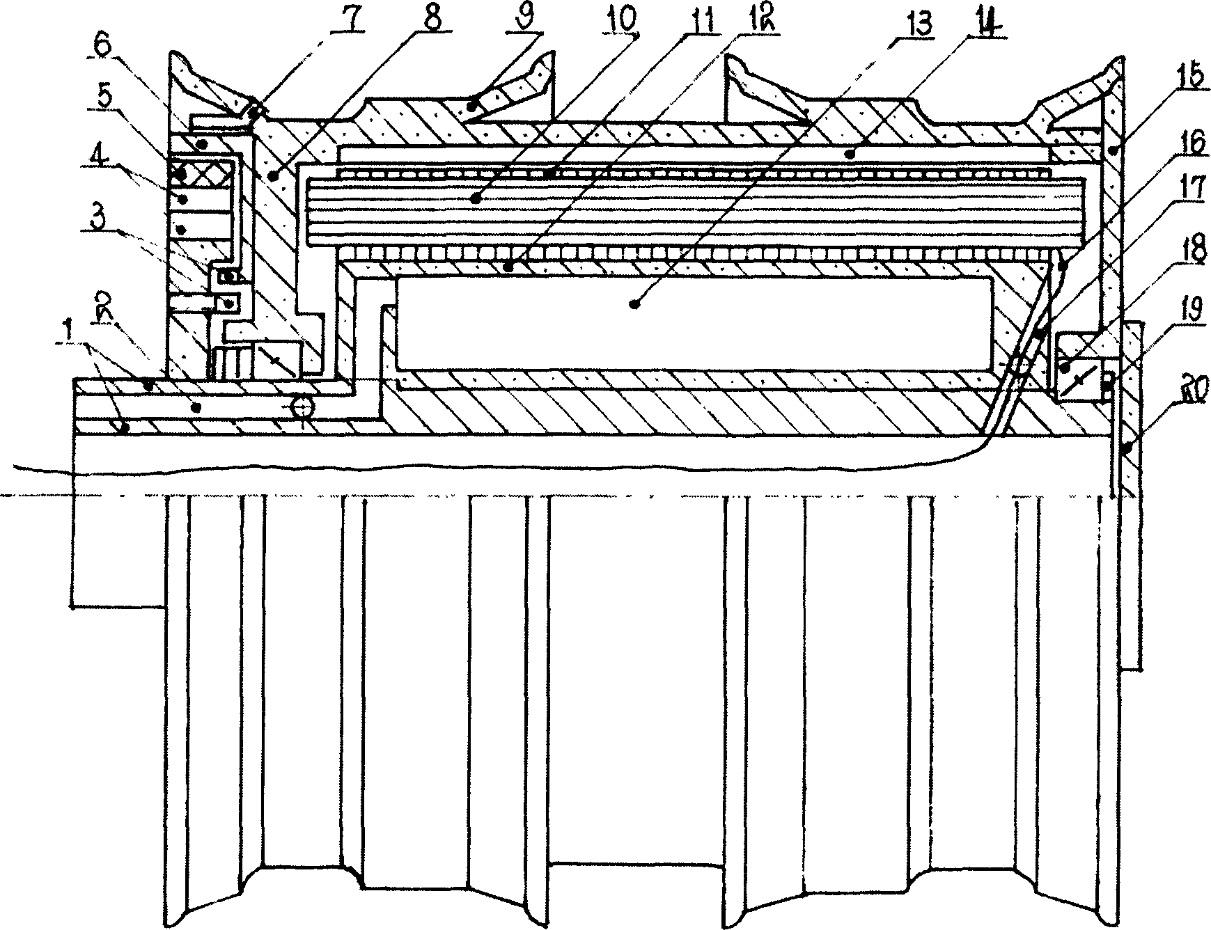
[0012] The three-stroke rotor permanent magnet variable frequency speed regulating motor is a rotor permanent magnet switch frequency conversion speed regulating three-phase motor. The stator and rotor are salient pole structures; the stator is made of silicon steel sheets, and the rotors are staggered in the order of N-S-N- It is inlaid with permanent magnets on the tile surface; the structure of its hub electric wheel is as follows: figure 1 Shown: The motor is an outer rotor type, and the stator winding is integrated with the motor shaft, that is, the wheel shaft. A cooling chamber 13 is provided between the hollow shaft 1 and the iron core 11. It is made of a carrier 12 cast from magnesium-aluminum alloy with good thermal conductivity and high strength. For the passage hole 17 of the wire 16 leading to the stator winding 10 through the wall of the cooling chamber, a simple concentrated excitation winding 10 is provided on the salient pole of the iron core 11, and the windi...


PUM


Abstract

The invention discloses a rotor permanent magnet conversion governing dynamo and its hub electric wheel. The rotor of the dynamo is to inlay permanent magnets in an order of N-S-N arranged with staggered intervals in the rotor taking the nonmagnetic material as a carrier to form a shielded projecting magnetic pole; a stator is a projecting pole of serial simple excitation winding four quadrants, which is made by piling silicon plates layer upon layer; a single-phase motor is continuous supplying power with frequency conversion, which only has an inhale stroke and an exhaust stroke; a three-phase motor, in which the adjacent two phases contemporarily in frequency conversion and alternatively provides an identical current, has an inhale stroke, an exhaust stroke and an indirect stroke; the motor speed is in direct ratio with the current frequency, and in inverse ratio with the number of the rotor magnetic poles. The hub electric wheel is an external rotor type of single-phase or three-phase rotor permanent magnetism frequency conversion governing dynamo. The wheel is a motor shell; the stator casts the core and axle used aluminium alloy to form a hollow cooling chamber and elicits the water supply and sewerage interlinked with outside world; the axel takes the motor shaft as a hollow; on brake frame, a sensor is installed on the axle; a brake drum is installed at the back-end body of the motor; and an induction tooth disc is installed on the back-end body.

Description

[0001] Field [0002] The invention relates to a rotor permanent-magnet variable-frequency speed-regulating motor and an electric wheel of an automobile hub, which belong to the electric automobile special motor manufacturing industry in the field of energy technology. [0003] The technical solution claimed in the present invention is limited to the technical field and industry. technical background [0004] The electric drive system is the heart of the electric vehicle. The technical solutions adopted at home and abroad mainly include DC motor system, induction motor-inverter system, permanent magnet motor system and synchronous reluctance motor system. The driving form is the transmission central bridge drive, Wheel-side deceleration motor drive, rim deceleration electric wheel drive, hub electric wheel drive, etc. Among them, the main disadvantage of the central bridge drive and wheel-side deceleration motor drive system is that the reducer and the motor occupy a large spa...

Claims


Application Information

Patent Timeline
Patent Type & Authority Applications(China)
IPC IPC(8): H02K1/14H02K1/20H02K1/27H02K7/102H02K7/14H02K21/12
Inventor 金胜虎
Owner 金胜虎
Why Eureka
Try Eureka