Fluid magnetic purifier
A purifier and fluid technology, applied in chemical instruments and methods, suction equipment, chemical/physical processes, etc., to achieve the effects of less resources, easy installation and portability, and low mass production costs
- Summary
- Abstract
- Description
- Claims
- Application Information
AI Technical Summary
Problems solved by technology
Method used
Image

Examples
Embodiment 1
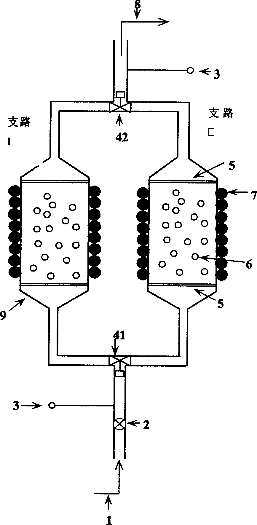
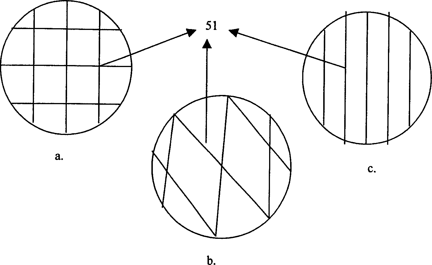
[0035] Prepare a layer of light-sensitive material on substrate materials such as silicon wafers, glass, ceramics, or metals, perform optical exposure according to the designed microstructure photomask, and form concave-convex results of light-sensitive materials on the substrate after development. Two sets of parallel microfluidic structures are prepared on the substrate by wet etching or dry etching, such as input and output flow channel ports, fluid pool fluid channels, etc., and two stainless steel wires are fixed in the middle of the inflow and outflow ports. 50 micron magnetic microsphere barrier structure, a three-way valve is installed on the input and output ends, and a peristaltic pump is connected to the input end to improve the power of the fluid. A rotating magnetic field is applied to the outer end of the fluid pool. After completing the preparation of various structures, the devices prepared above are packaged with silicon wafers, glass plates, plastics, metal o...
Embodiment 2
[0037] Prepare a layer of light-sensitive material on substrate materials such as silicon wafers, glass, ceramics, or metals, according to the design
[0038] The planned microstructure photomask is subjected to optical exposure, and after development, the unevenness of the light-sensitive material is formed on the substrate. A layer of polymerizable polymer material (such as plastic, rubber, etc.) is coated on the above-mentioned concave-convex structure. After the polymer material is solidified, it is separated from the substrate, and two sets of parallel microfluidic structures are prepared on the surface of the polymer material, such as input and output channel ports, fluid pool fluid channels, etc., and the inflow and outflow ports are fixed in the middle Two magnetic microsphere barrier structures with a pore size larger than 50 microns woven by stainless steel wire, a three-way valve is installed at the input and output ends, and a peristaltic pump is connected to the i...
Embodiment 3
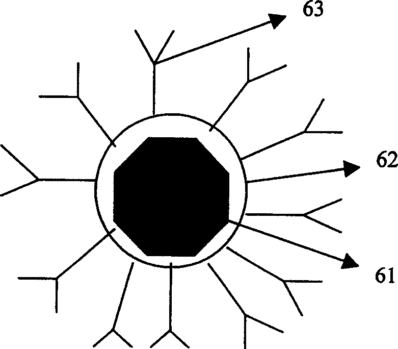
[0040] According to the designed microstructure, the corresponding plastic or rubber precision molds are prepared. Direct application of micro-casting technology to prepare various plastic or rubber microfluidic structures, such as input and output channel ports, fluid blocking structures, fluid pools, fluid channels, etc. Anti-low-density lipoprotein antibodies are immobilized on the surface of the magnetic microspheres in the fluid pool to capture harmful substances (such as harmful proteins, viruses, or harmful cells, etc.). After the preparation of various structures is completed, assembly and packaging are carried out, and the materials used should be non-biologically toxic materials. After the device is packaged, the surface of the material inside the device is chemically treated to make it anti-coagulant. The whole set of equipment is sterilized, and the aseptically operated magnetic microspheres connected with proteins (such as antibodies, receptors, antigens) are pla...
PUM
 Abstract
Description
Claims
Application Information
 - R&D
- Intellectual Property
- Life Sciences
- Materials
- Tech Scout
- Unparalleled Data Quality
- Higher Quality Content
- 60% Fewer Hallucinations
Browse by: Latest US Patents, China's latest patents, Technical Efficacy Thesaurus, Application Domain, Technology Topic, Popular Technical Reports.
© 2025 PatSnap. All rights reserved.Legal|Privacy policy|Modern Slavery Act Transparency Statement|Sitemap|About US| Contact US: help@patsnap.com