

Water cooling electromagnetic copper type directional solidification method of titanium base alloy
A directional solidification, titanium-based alloy technology, applied in the field of directional solidification of metals, can solve problems such as low production efficiency, reduced drawing speed, and difficult to obtain cooling rate
- Summary
- Abstract
- Description
- Claims
- Application Information
AI Technical Summary
Problems solved by technology
Method used
Image

Examples
specific Embodiment approach 1
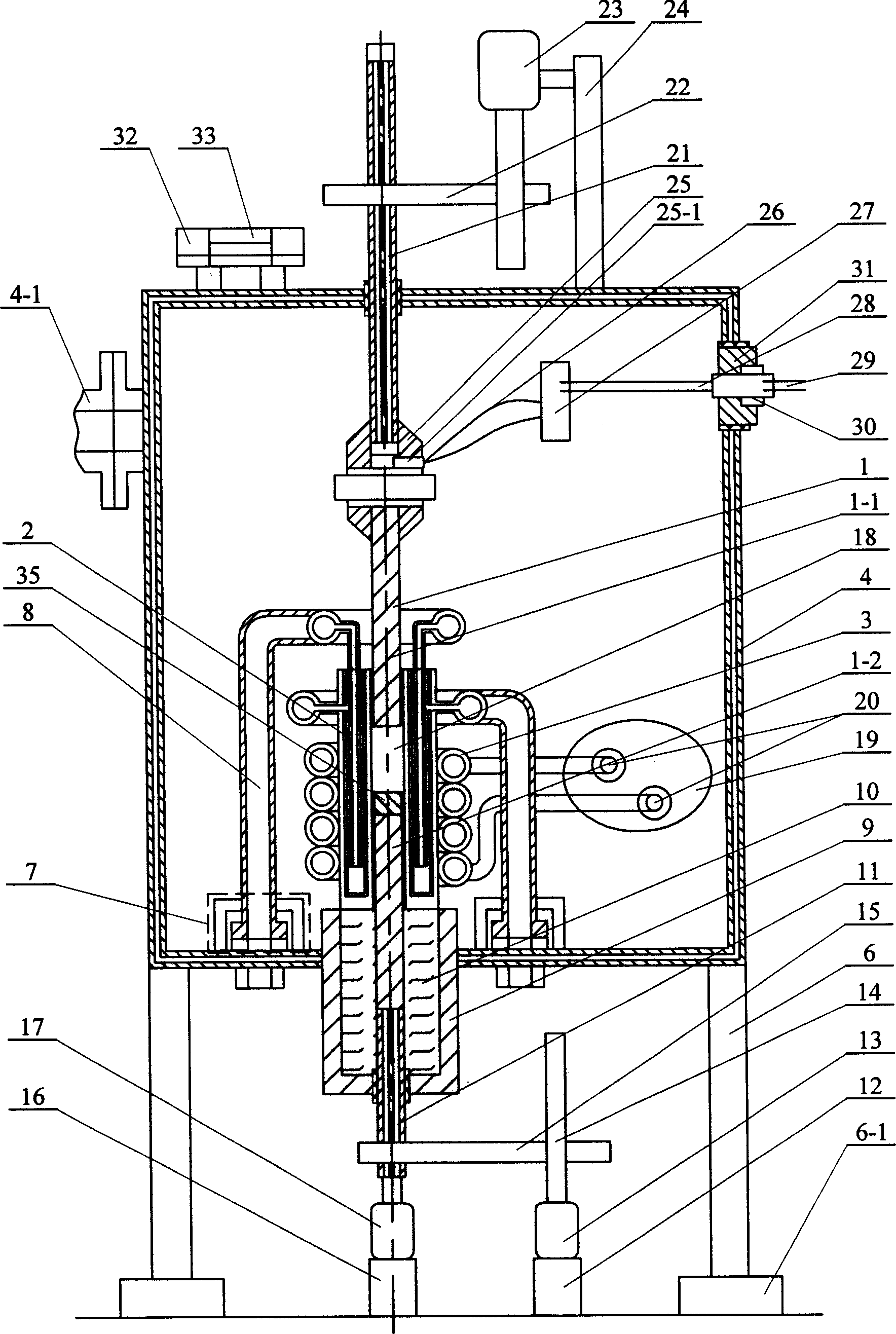
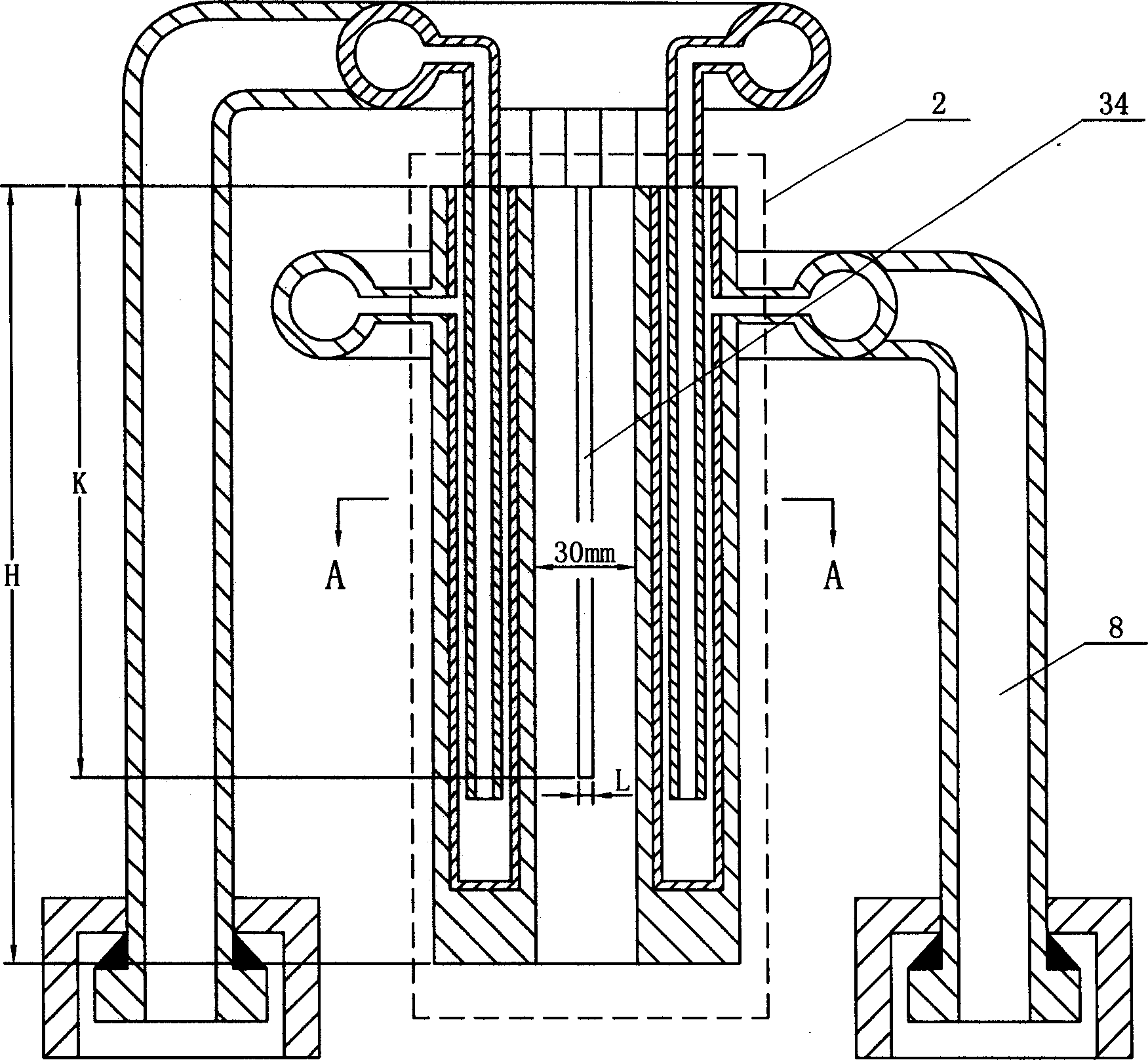
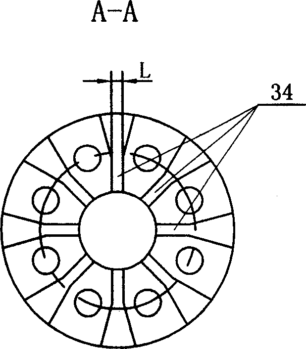
[0014] Specific implementation mode one: the work process of this embodiment mode is as follows: refer to figure 1, the furnace body 4 is installed on the support frame 6 by bolts, and the support frame 6 is horizontally connected and stably fixed on the ground with anchor bolts 6-1; there are two groups of circulating water channels 7 at the inner bottom of the furnace body 4, and the circulating water Channel 7 communicates furnace body 4 with water pipe 8, and the other end of water pipe 8 communicates with water-cooled copper type 2, thereby the waterway of furnace body is communicated with the waterway of water-cooled copper type; through the connection of copper pipe 8 and circulating water channel 7, also It can support the water-cooled copper mold 2; the internal water-cooled crystallizer 9 is fixed at the center of the bottom of the furnace body 4 by welding, and its bottom extends to the outside of the furnace body 4 to provide a forced solidification for the directio...
specific Embodiment approach 2
[0017] Specific Embodiment Two: This embodiment is to adopt the method of the present invention to implement the directional solidification process on titanium-based alloys. The alloy composition is Ti-6wt%Al-4wt%V. This is a general-purpose titanium alloy, which accounts for the current industrial titanium alloy usage. More than 90% of the alloy was directional solidified under the conditions of speed 1mm / min and power 48KW. After longitudinal planing of the obtained sample, after grinding and corrosion, there were three large columnar grains on the entire planing surface, and the solidification interface For the plane interface, directional solidification tissue can be obtained. The tensile strength of the alloy after directional solidification does not change much, and the elongation increases from 8.2% to 12.7%.
specific Embodiment approach 3
[0018] Specific Embodiment Three: This embodiment is to use the method of the present invention to implement a directional solidification process on another titanium-based alloy. The alloy composition is Ti-36wt% Al alloy, which is a titanium-based intermetallic compound material containing a high amount of aluminum. , which is a new type of light-weight high-temperature-resistant structural material, has broad application prospects in high-temperature components such as aero-engines. When the pulling speed is 0.2mm / min and the power is 48KW, directional solidification of this compound material can also be obtained. The solidification structure shows that the directional solidification structure with solidification characteristics can be obtained under the condition of low discharge speed. The tensile strength is increased from 245MPa as cast to 287MPa, and the elongation is increased from 0.1% to 0.35%.
PUM
| Property | Measurement | Unit |
|---|---|---|
| Tensile strength | aaaaa | aaaaa |
Abstract
Description
Claims
Application Information