

Adhesive type optical film and image display
An optical film and adhesive technology, applied in optics, optical components, lighting devices, etc., can solve problems such as display defects, inability to adhere, and display quality degradation
- Summary
- Abstract
- Description
- Claims
- Application Information
AI Technical Summary
Problems solved by technology
Method used
Image

Examples
Embodiment 1
[0091] (production of optical film)
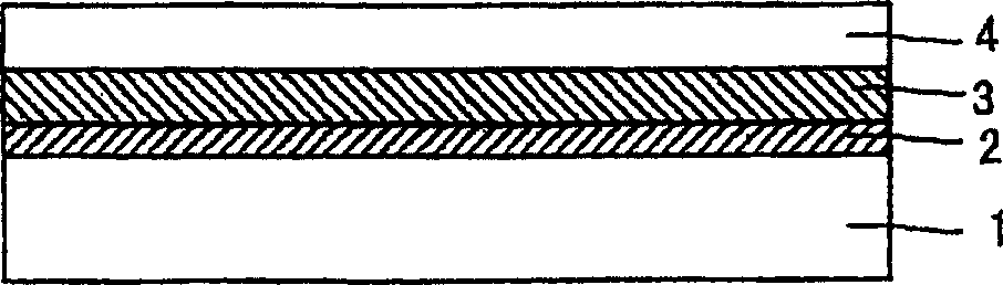
[0092] A polarizer was obtained by stretching an 80 μm thick polyvinyl alcohol film 5 times in an iodine aqueous solution at 40° C. and then drying it at 50° C. for 4 minutes. A triacetyl cellulose film was bonded to both sides of the polarizer using a polyvinyl alcohol type adhesive to obtain a polarizing plate.
[0093] (formation of adhesion-promoting layer)
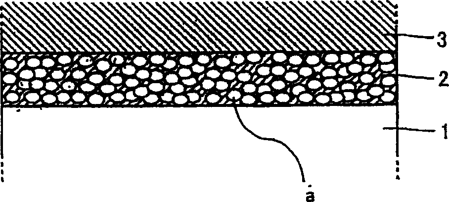
[0094] As the polyurethane resin latex, Adeka Bontighter HUX290H (average particle size of the latex is about 42nm) manufactured by Asahi Denka Kogyo Co., Ltd. was used, and it was prepared with a mixed solvent of water: butyl cellosolve = 3:1 (volume ratio) so that the solid content was diluted. to a 5% solution. The solution was coated on the above polarizer using a wire rod #5, and the volatiles were allowed to evaporate. The thickness of the evaporated adhesion-promoting layer was observed by the TEM ultra-thin film slice method, and the result was 1000 nm, and it was confi...
Embodiment 2
[0100] (optical film)
[0101] A corona-treated film (contact angle with water: 71 degrees) was used for a retardation plate (100 μm) using a biaxially stretched norbornene-based resin (manufactured by JSR, Arton).
[0102] (formation of adhesion-promoting layer)
[0103] As the polyethyleneimine adduct of acrylic acid / styrene copolymer latex, POLYMENT SK1000 (the average particle diameter of the latex is about 100nm) of Nippon Shokubai Co., Ltd. was used, and it was mixed with water: isopropanol=1:3 ( volume ratio) mixed solvent to prepare a solution in which the solid content was diluted to 5%. The solution was coated on the above-mentioned retardation plate using a wire rod #5, and then the volatile substances were allowed to evaporate. The thickness of the evaporated adhesion-promoting layer was observed by the TEM ultra-thin film slice method, and the result was 800nm, and it was confirmed that there were 4-5 latex particles in the thickness direction.
[0104] (Produc...
Embodiment 3
[0107] (production of optical film)
[0108] A solution of polycarbonate (PC) flakes dissolved in methylene chloride was evenly cast on a smooth SUS plate, and dried in a solvent atmosphere to prevent condensation on the surface. After sufficient drying, the PC was peeled off from the SUS plate, and then dried in a hot air circulation oven to obtain a PC unstretched film (30 μm). This film was stretched 1.2 times while heating, and corona-treated to obtain a PC retardation film (contact angle with water: 73 degrees).
[0109] (formation of adhesion-promoting layer)
[0110] An adhesion-promoting layer was formed on the above-mentioned PC retardation plate in the same manner as in Example 2. The thickness of the evaporated adhesion-promoting layer was observed by the TEM ultra-thin film slice method, and the result was 800nm, and it was confirmed that there were 4-5 latex particles in the thickness direction.
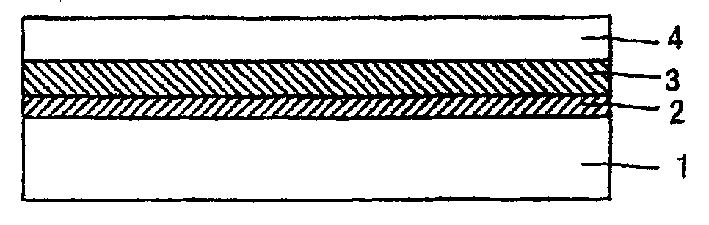
[0111] (Production of adhesive optical film)
[0112] The relea...
PUM
| Property | Measurement | Unit |
|---|---|---|
| thickness | aaaaa | aaaaa |
| glass transition temperature | aaaaa | aaaaa |
| thickness | aaaaa | aaaaa |
Abstract
Description
Claims
Application Information