Pulsed electron beam polymerization
An electron beam, pulsed technology used in the field of polymerizing monomers and/or oligomers to achieve short residence times, low cost, and practical productivity
- Summary
- Abstract
- Description
- Claims
- Application Information
AI Technical Summary
Problems solved by technology
Method used
Image
Examples
example 1
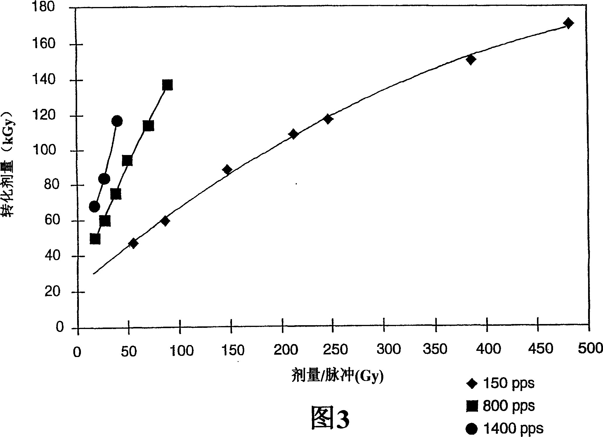
[0183] Example 1 illustrates the effect of dose per pulse on the total dose necessary to obtain an extrapolated conversion of about 97%.
[0184] Pressure-sensitive adhesive samples were prepared using Paste A by pulsed electron beam irradiation at 0 °C. The pulse source used in sample A is PYXIS source, and the pulse source used in samples B-P is NSRC source. Pulse frequency and dose per pulse are varied and total dose is calculated.
[0185] The percent conversion was measured for each coated sample. The extrapolated conditions for a conversion of about 97% are reported in Table 1.
[0186] Example
[0187]As shown in Table 1 and illustrated in Figure 3, the dose required to achieve approximately 97% conversion increases almost linearly with dose per pulse at all pulse frequencies. The loss of energy efficiency with increasing dose per pulse is more pronounced at high pulse frequencies. The increase in the total dose required to achieve about 97% conversion was...
example 2
[0192] Example 2 illustrates the effect of low dose per pulse and high dose rate on the ability to obtain about 97% conversion.
[0193] Samples for Example 2 were prepared as in Example 1 using various pulse frequencies and doses per pulse from both sources. The process variables and resulting dosage values necessary to obtain a polymerized pressure sensitive adhesive coating with about 97% conversion are shown in Table 3.
[0194] Example
[0195] As shown in Table 3 and illustrated in Figure 4, using a modified slurry similar to that used in Example 1, a conversion of about 97% was obtained with a high dose rate and a low dose per pulse. Consistent with the results of Example 1, the above results illustrate that the total dose required for high conversion increases as the pulse frequency increases. However, with increasing pulse frequency, the loss of conversion efficiency is significantly reduced when the pulse frequency is increased beyond 500-600 pps, especi...
Embodiment 3
[0197] Example 3 illustrates the effect of pulse conditions on the irradiation time required to obtain about 97% conversion.
[0198] Samples 3D, 3F, 3H, 3R and 3X of Example 3 were prepared as in Example 1 using various pulse frequencies and doses per pulse. The remaining samples are the same as in Examples 1 and 2 according to the reference numerals. The pulse source for sample U was the PYXIS source and the pulse source for samples A-T and V-AA was the NSRC source. The process variables necessary to obtain a polymerized pressure sensitive adhesive coating with a conversion of about 97% are shown in Table 4.
[0199] Example
[0200] Comparative samples were prepared by successively irradiating the prepared samples from one of the two slurries at different dose rates. Both slurry A (88:12) and slurry B (90:10) were used. The irradiation conditions and compositions are shown in Table 5.
[0201] Example
[0202] The data in Tables 4 and 5, shown in Fig...
PUM
| Property | Measurement | Unit |
|---|---|---|
| peel strength | aaaaa | aaaaa |
| thickness | aaaaa | aaaaa |
| thickness | aaaaa | aaaaa |
Abstract
Description
Claims
Application Information
 - R&D
- Intellectual Property
- Life Sciences
- Materials
- Tech Scout
- Unparalleled Data Quality
- Higher Quality Content
- 60% Fewer Hallucinations
Browse by: Latest US Patents, China's latest patents, Technical Efficacy Thesaurus, Application Domain, Technology Topic, Popular Technical Reports.
© 2025 PatSnap. All rights reserved.Legal|Privacy policy|Modern Slavery Act Transparency Statement|Sitemap|About US| Contact US: help@patsnap.com


