
Spatial light modulator and projector

A technology of spatial light modulation and modulation unit, applied in projection devices, optics, optical components, etc., can solve the problem of image contrast reduction and achieve high contrast

Inactive Publication Date: 2005-08-10
SEIKO EPSON CORP
View PDF1 Cites 5 Cited by
  • Summary
  • Abstract
  • Description
  • Claims
  • Application Information

AI Technical Summary

Problems solved by technology

Therefore, there is a problem that the contrast of the image is lowered

Method used


Image

  • Spatial light modulator and projector
  • Spatial light modulator and projector
  • Spatial light modulator and projector

Examples


Embodiment 1

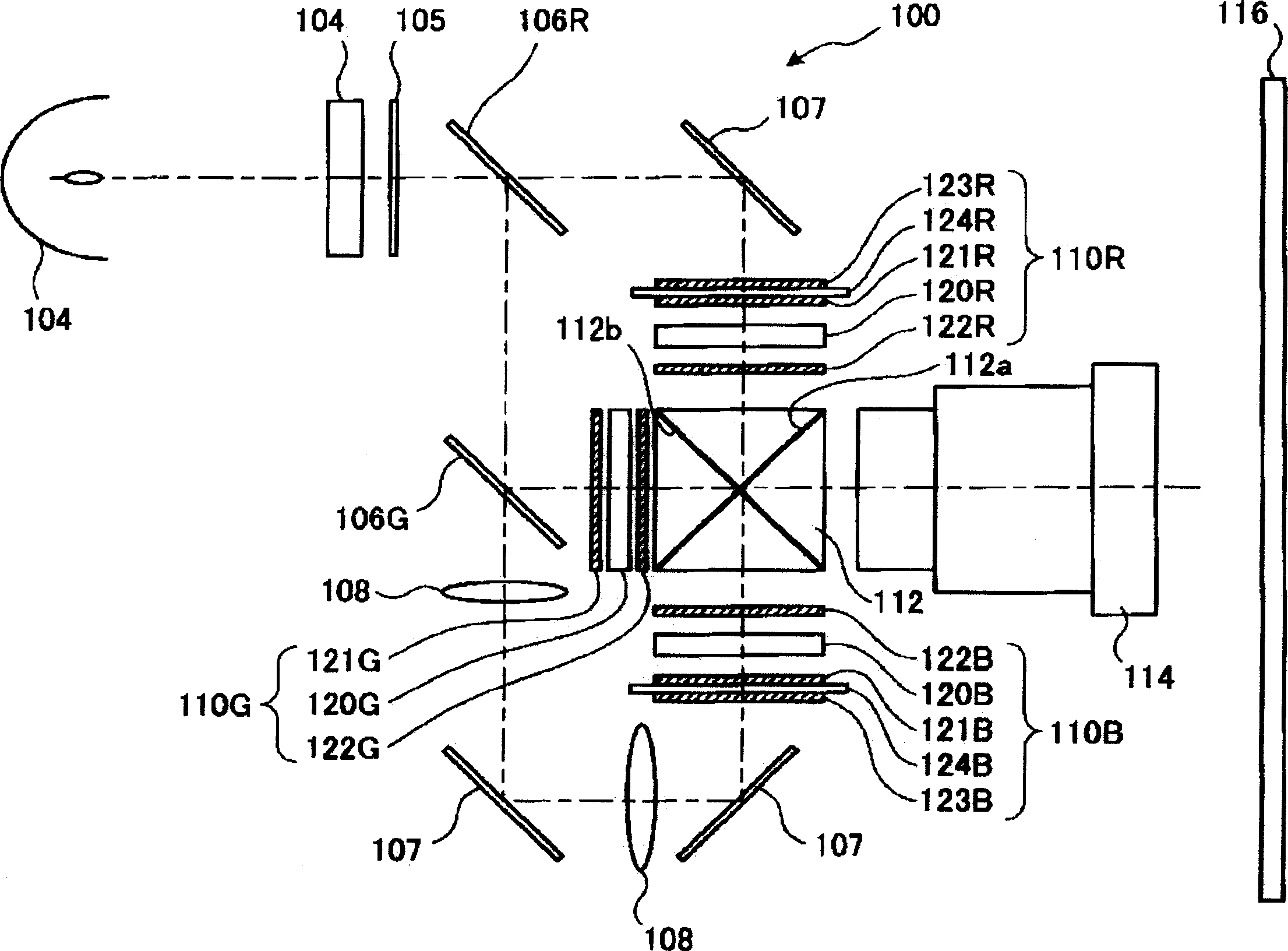
[0040] figure 1 A schematic configuration of projector 100 according to Embodiment 1 of the present invention is shown.

[0041] Description of the projector as a whole.

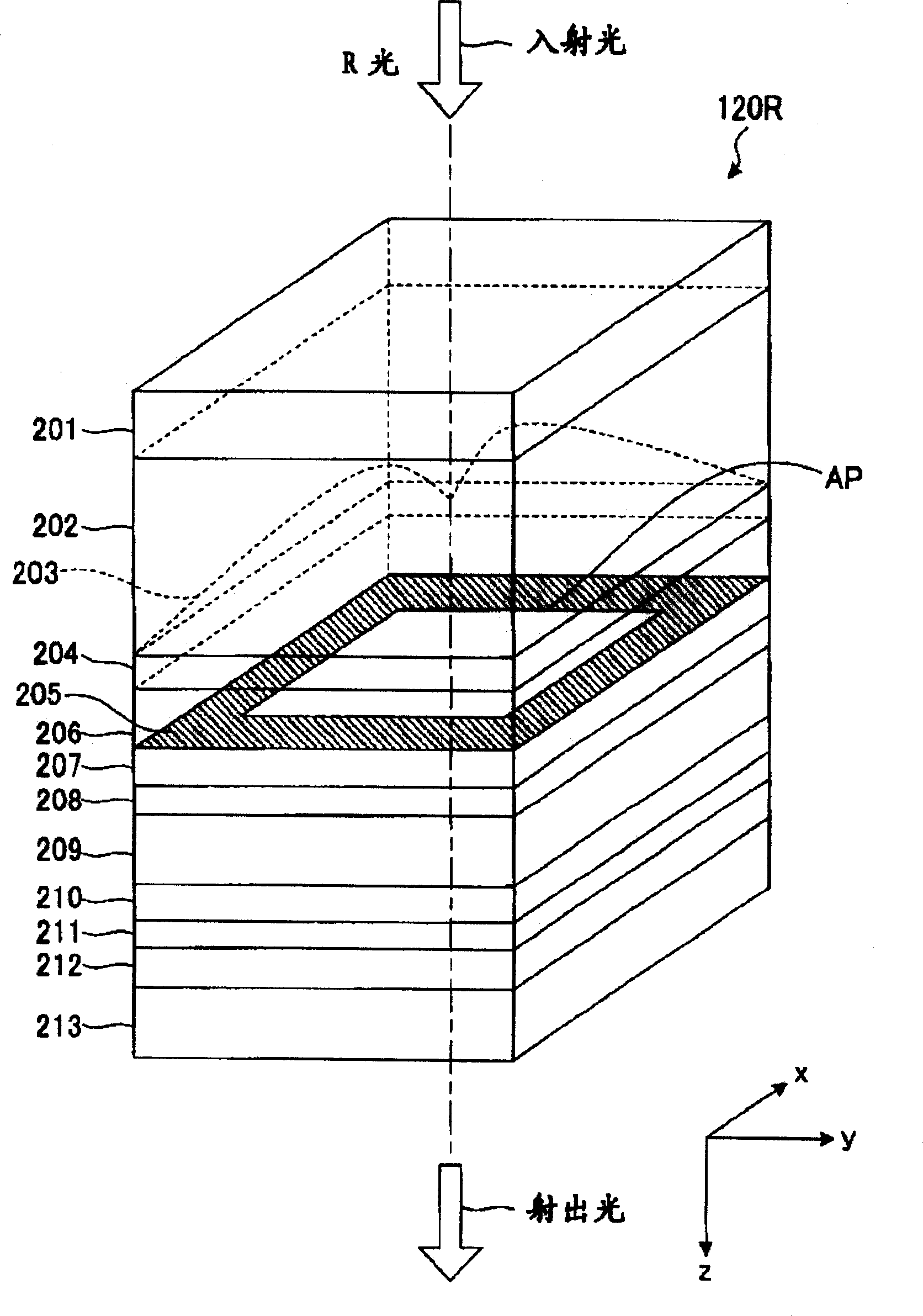
[0042] First, refer to figure 1 A schematic configuration of a projector according to Embodiment 1 of the present invention will be described. Next, refer to figure 2 The accompanying drawings illustrate the characteristic structure of this embodiment. First, in figure 1 Among them, the ultra-high pressure mercury lamp 101 as the light source unit supplies red light (hereinafter referred to as "R light") as the first color light, green light (hereinafter referred to as "G light") as the second color light, and red light as the third color light. blue light (hereinafter referred to as "B light") light. The integrator 104 equalizes the illuminance distribution of the light from the ultra-high pressure mercury lamp 101 . The light whose illuminance distribution has been made uniform is converted by the ...

Embodiment 2

[0071] Figure 6 It is a perspective cross-sectional view showing the structure of a part of the liquid crystal panel 620R in the projector of the second embodiment. In the liquid crystal panel 620R, a plurality of opening regions AP are arranged substantially orthogonally in a grid. The opening region AP as a pixel opening is a rectangular opening formed on the black matrix 205 having a light-shielding function. The opening area AP corresponds to one pixel. exist Figure 6 In , only a part of one opening area AP among the plurality of opening areas AP of the liquid crystal panel 620R is shown. Since the structure of the liquid crystal panel 620R corresponding to the other opening area and Figure 6 The structures shown are the same, so repeated explanations are omitted. In addition, the same code|symbol is attached|subjected to the same part as the above-mentioned Example 1, and repeated description is abbreviate|omitted.

[0072] The microlens element 603 of this embod...


PUM


Abstract

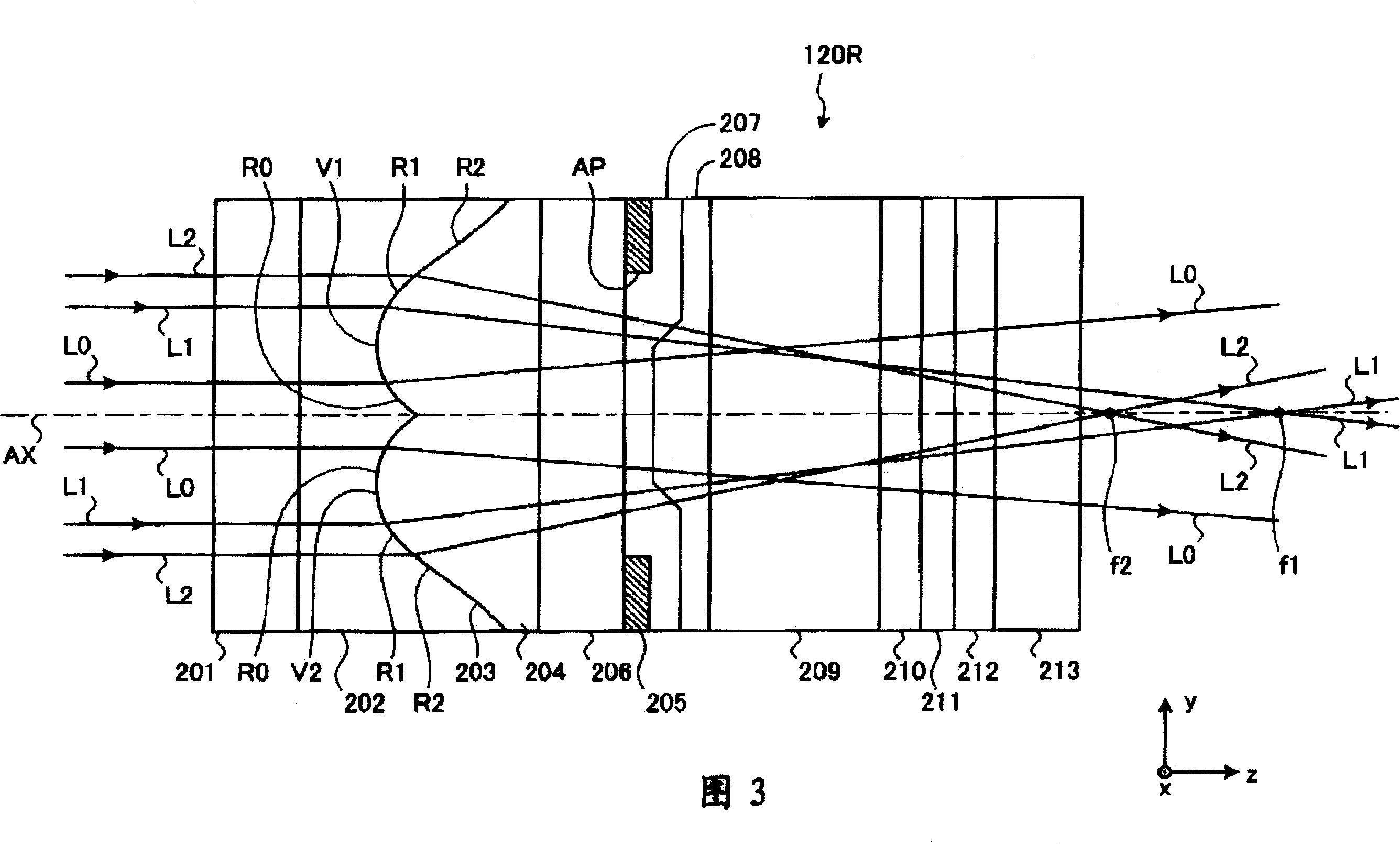
The invention provides a spatial light modulator and projector with low cost and long service life for obtaining a high contrast image with a high light utilization efficiency. The spatial light modulator comprises a plurality of pixel opening areas (AP), a liquid crystal layer (209) for modulating and transmitting lights according to the image signal, and a plurality of micro lens components (203) capable of condensing the incident light and passing through the opening area (AP) on the incident side of the liquid crystal layer (209) and the opening area AP counterpart arrangement. Moreover, the micro lens components (203) have a plurality of focus positions (f1) and (f2) for each different roughly wheel shaped parts (R1) and (R2) corresponding to the optical axis as a center; the focus position (f2) of every wheel shaped part (R2) in a plurality of wheel shaped parts is positioned at a position closer to the micro lens component (203) based on the wheel shaped part (R2) and closed to one side of the optical axis (AX); every focus position of a plurality of focus positions (f1) and (f2) is closer to the ejaculating side compared with the liquid crystal layer (209).

Description

technical field [0001] The present invention relates to a spatial light modulation device, particularly a liquid crystal type spatial light modulation device, and a projector equipped with the same. Background technique [0002] Home use of projectors is expanding in recent years. Therefore, it is expected that the spatial light modulation device of the projector is inexpensive, has a long life, and can obtain high-contrast images with high light utilization efficiency. As a representative example of the spatial light modulation device, for example, a liquid crystal panel is used. On the liquid crystal panel, various wirings such as data lines, scanning lines, and capacitor lines, and various electronic components such as thin film transistors and thin film diodes are provided in the image display area. Therefore, in each pixel, the area through which light for image display can be transmitted or reflected is limited by the presence of various wirings, electronic component...

Claims


Application Information

Patent Timeline
Patent Type & Authority Applications(China)
IPC IPC(8): G02F1/13G02B3/10G02B5/30G02F1/1335G03B21/00H04N5/74
CPCG02B5/3016
Inventor 内川大介米窪政敏上岛俊司水迫和久
Owner SEIKO EPSON CORP
Learn More