Novel material

a technology of new materials and materials, applied in the field of substrates, can solve the problems of new materials and structures which are otherwise impossible to fabricate, and achieve the effects of increasing refractive index and/or waveguide structures, facilitating ion-implantation, and increasing sensitivity

Inactive Publication Date: 2020-07-30
UNIV OF LEEDS
View PDF0 Cites 0 Cited by
  • Summary
  • Abstract
  • Description
  • Claims
  • Application Information

AI Technical Summary

Benefits of technology

[0006]Thus, according to a first aspect of the invention there is provided a substrate comprising an ion-implanted layer wherein the penetration depth of the implanted ions is at least 50 nm, or at least 200 nm, for example at least 500 nm. The applicants have also found that the process provides a substantially uniform distribution density of the implanted ions in the implanted layer rather than the density profile showing a peak followed by a drop off in implanted ion density, in a manner which the ion depths transcend conventional diffusion and high-energy ion implantation, due to major structural barriers for ion diffusion / implantation. The applicants have also found that the process provides a very rapid and substantially discontinuous termination in the distribution density of the implanted ions at the terminal boundary of the implanted layer within the substrate, rather than the density profile showing a gradual and continuous drop-off in implanted ion density. The ion distribution, or concentration level, may fall from the average (e.g. substantially uniform) level of the layer to a substantially ion-free concentration level or distribution, over a distance of about 30 nm or less, or more preferably about 20 nm or less or yet more preferably about 10 nm or less. This enables a sharply-defined inner terminal “edge” to be formed in the implanted layer.
[0122]The term ‘waveguide’ refers to any element which facilitates transmission of light therethrough, such as guided transmission. The term includes a reference to any element which facilitates transmission of light into a material of interest and facilitates measurement of light which is retrieved from the material of interest.

Problems solved by technology

This observation has the potential to produce new materials and structures which are otherwise impossible to fabricate.

Method used


Image

  • Novel material
  • Novel material
  • Novel material

Examples


example 1

Implantation Into Silica Glass

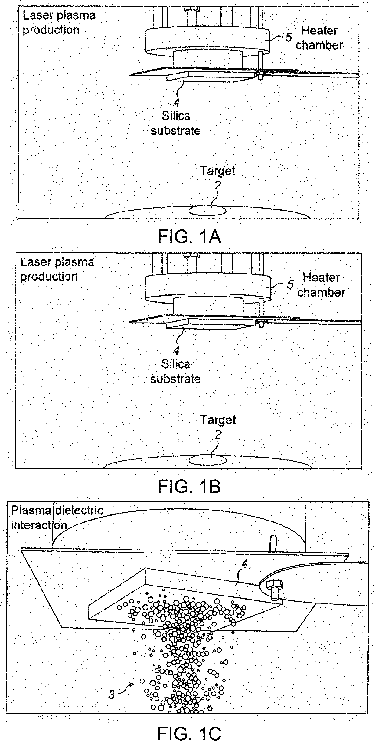
[0142]Multi-ion implantation into silica glass 4 was produced via femtosecond laser ablation of an erbium doped tellurite glass target containing zinc and sodium. A Ti-sapphire femtosecond laser 1 operating at a wavelength of 800 nm with 100 fs pulse width and a maximum repetition rate of 1 kHz (Coherent Inc, Santa Clara, Calif., USA) was used to ablate the glass target 2 generating an expanding plasma plume 3 consisting of multiple metal ions (multi-ion). A tellurite glass target with a molar composition of 79.5TeO2 : 10ZnO0:10Na2O: 0:0.5Er2O3 produces multiple ions of Te, Zn, Na and Er, which diffuse into the silica glass substrate 4 under certain process conditions. The silica glass substrate was coupled to a heater chamber arranged to heat the substrate to a desired temperature. The ablation, plasma production and the multi-ion implantation process are schematically shown in FIG. 1A-1C.

[0143]Experiments were carried by varying the laser energy, repe...


PUM

PropertyMeasurementUnit
distanceaaaaaaaaaa
depthaaaaaaaaaa
depthaaaaaaaaaa

Abstract

The present invention relates to a substrate comprising an ion-implanted layer, for example a cation, wherein the ion implanted layer has a substantially uniform distribution of the implanted ions at a significantly greater depth than previously possible, to a well-defined and sharp boundary within the substrate. The invention further comprises said substrate wherein the substrate is a silicon based substrate, such as glass. The invention also comprises the use of said material as a waveguide and the use of said material in measurement devices.

Description

RELATED APPLICATIONS[0001]This is a continuation-in-part application of U.S. application Ser. No. 14 / 377,403, filed Aug. 7, 2014, which is a 371 application of International Application No. PCT / GB2013 / 050300 filed Feb. 8, 2013, which claims the benefit of priority of United Kingdom Patent Application No. 1202128.3 filed Feb. 8, 2012. Each of the foregoing applications is hereby incorporated herein by reference.FIELD OF THE INVENTION[0002]The present invention relates to a substrate comprising an ion-implanted layer, for example a cation, wherein the ion implanted layer has a uniform distribution of the implanted ions at a significantly greater depth than previously possible. The invention further comprises said substrate wherein the substrate is a silicon based substrate, such as glass. The invention may also comprise the use of said material as a waveguide and / or the use of said material in measurement devices.BACKGROUND[0003]Femtosecond pulsed laser plasma deposition (fs-PLD) is a...

Claims


Application Information

Patent Timeline
Patent Type & Authority Applications(United States)
IPC IPC(8): C03C23/00C03C3/04C23C14/32C23C14/48C23C14/22A61B5/1455C23C14/28G02B6/12
CPCG02B2006/12061G02B2006/12188A61B5/1455C23C14/48C03C23/0055Y10T428/315Y10T428/31C23C14/28C23C14/32C23C14/221C03C3/04
Inventor JOSE, GINFERNANDEZ, TONEY TEDDYGRANT, PETER JOHNJHA, ANIMESHSAHA, SIKHASTEENSON, DAVID PAUL
Owner UNIV OF LEEDS
Why Eureka
Try Eureka