
Servo motor driven digital control plate bending machine

A servo motor and bending machine technology, applied in the direction of digital control, electrical program control, etc., can solve the problems of difficulty in realizing automation and digital control operation, difficulty in adapting to production requirements, oil leakage of machine tools, etc., to reduce loading and unloading and stacking time, reduced technical proficiency requirements, smooth running effects

Inactive Publication Date: 2005-10-19
吉素琴
View PDF0 Cites 7 Cited by
  • Summary
  • Abstract
  • Description
  • Claims
  • Application Information

AI Technical Summary

Problems solved by technology

[0003] The mechanical bending machine uses a three-phase asynchronous motor as the driving power of the slider, and uses the clutch to change the speed, that is, the speed is changed according to the following process requirements: the slider starts to move down quickly, that is, it runs at high speed. When the bending operation is performed, the slider moves down slowly. When the slider returns, it runs at high speed. The disadvantage of this structure is that it has poor flexibility, and it is difficult to realize automation and digital control operations. Therefore, it is difficult to adapt to the current production requirements and has been eliminated in recent decades.
[0004] The hydraulic bending machine is the trend of development in recent decades. The slider moves in a straight line, and the oil cylinder is arranged on the wall panels on both sides. It is relatively easy to connect with the numerical control system. However, when loading and unloading, the oil pump is still working, so In terms of wasting energy, the hydraulic system of the machine tool may not leak oil temporarily, but in the long run, the machine tool will always leak oil
What's more, after the hydraulic system works for a certain period of time, oil needs to be changed, which will cause environmental pollution

Method used


Image

  • Servo motor driven digital control plate bending machine
  • Servo motor driven digital control plate bending machine
  • Servo motor driven digital control plate bending machine

Examples


Embodiment Construction

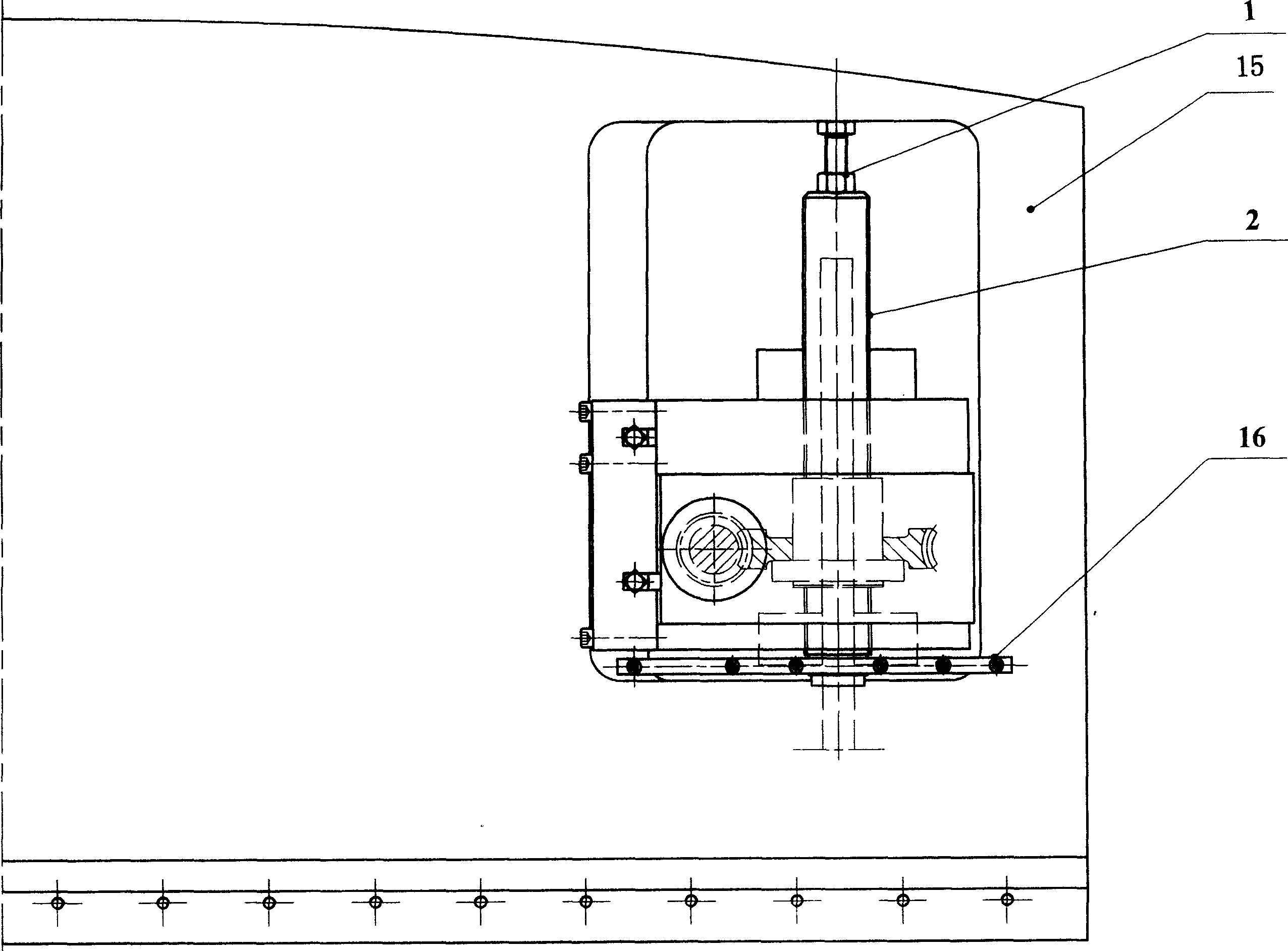
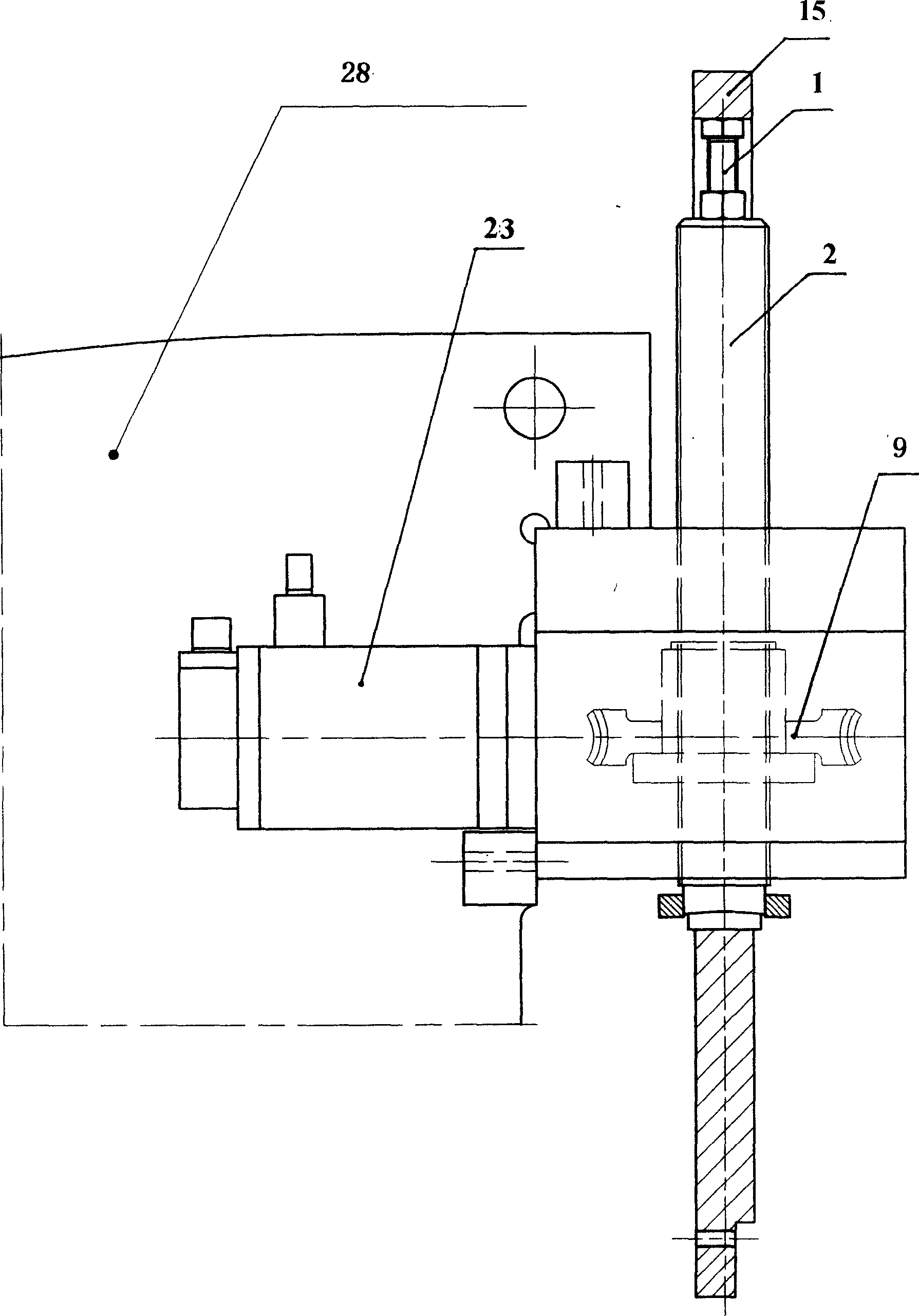
[0055] see Figure 5 , according to the length and thickness of the sheet, the shape of the machine tool, the mold and other data, the numerical control system (17) of the CNC bending machine automatically calculates the stroke of the slider (15), and when it is connected to the slider (15) and moves downward After the signal, the numerical control system (17) is respectively connected with the left servo motor driver (18) and the right servo motor driver (22) through the signal channel of ± 10 volts and sends out the instruction of running, and is respectively connected to the left servo motor driver (22) according to the size of the signal. Servomotor (19) and right servomotor (23), and control the speed of left servomotor (19) and right servomotor (23) running speed, left servomotor (19) and right servomotor (23) directly and left respectively The encoder (20) is connected with the right encoder (24) and its rotation state is converted into a square wave signal respectively...


PUM


Abstract

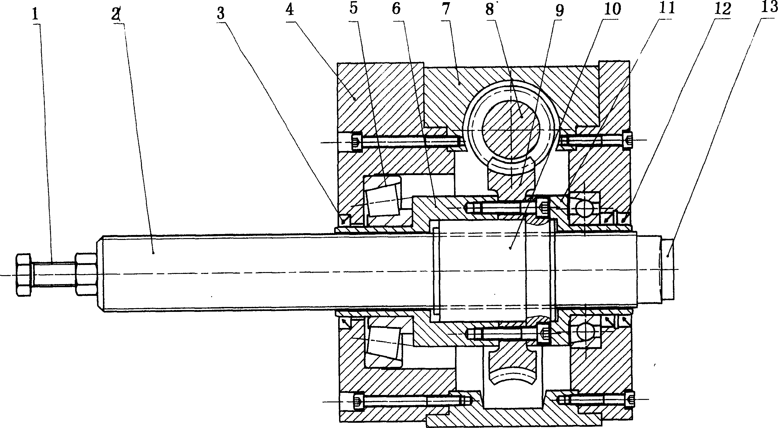
The servo motor driven digitally controlled plate bending machine belongs to the field of digitally controlled machine tool. The plate bending machine consists of computerized digital control system, right and left servo motor drivers, right and left motors, right and left coders, right and left grating rules, right and left worm gear transmission pairs, nut, ball lead screw, block and frame connected together. The present invention s high efficiency, low power consumption and environment friendship.

Description

Technical field: [0001] The servo motor-driven numerical control sheet metal bending machine of the present invention belongs to the field of digitally controlled machine tools. Background technique: [0002] According to the driving mode of the slider, the sheet metal bending machine can be divided into mechanical bending machine and hydraulic bending machine. [0003] The mechanical bending machine uses a three-phase asynchronous motor as the driving power of the slider, and uses the clutch to change the speed, that is, the speed is changed according to the following process requirements: the slider starts to move down quickly, that is, it runs at high speed. When the bending operation is performed, the slider moves down slowly. When the slider returns, it runs at high speed. The disadvantage of this structure is that it has poor flexibility, and it is difficult to realize automation and digital control operation. Therefore, it is difficult to adapt to the current producti...

Claims


Application Information

Patent Timeline
IPC IPC(8): B21D5/00G05B19/18
Inventor 叶兵史惊东冷志斌吉素琴
Owner 吉素琴
Learn More