Superheated steam drying method for sludge and drying equipment

A technology of superheated steam and drying method, applied in the direction of dehydration/drying/concentrating sludge treatment, etc., can solve the problems of complicated drying process and equipment, large heat loss of drying exhaust gas, poor drying process economy, etc., to shorten the drying time, fuel The effect of high operating cost and reduced heat exchange area

Inactive Publication Date: 2005-10-26
JIANGSU TIANYING ENVIRONMENTAL PROTECTION ENERGY COMPLETE EQUIP CO LTD +1
View PDF0 Cites 19 Cited by
  • Summary
  • Abstract
  • Description
  • Claims
  • Application Information

AI Technical Summary

Problems solved by technology

The drying medium of direct drying is usually the hot flue gas produced by fuel or waste combustion. The advantage is that the process flow is simple and the processing capacity of a single machine is large. Odor-causing substances must be deodorized before they can be discharged, and the heat loss of the exhaust gas is also very large, resulting in poor economic efficiency of the drying process
Indirect drying, the heat required for drying is transferred to the sludge through heat conduction, instead of using drying medium, the advantage is that there is no danger of explosion and fire, the amount of tail gas produced by drying is small, the drying thermal efficiency is high, and the operating cost of tail gas deodorization treatment is relatively low. Low, the economy of drying treatment is better, the shortcoming is that the drying process and equipment are more complicated, the processing capacity of a single machine is small, and it is easy to stick to the wall, so it is not suitable for the sludge with strong adhesion

Method used


Image

  • Superheated steam drying method for sludge and drying equipment
  • Superheated steam drying method for sludge and drying equipment

Examples


Embodiment 1

[0012] A sludge drying method using superheated steam as the drying medium, using a heat exchanger to recover the sensible heat and latent heat in the drying tail steam, making it exchange heat with water, and then heating it into superheated steam, then passing it into a closed direct In the type dryer, the superheated steam exchanges heat and mass with the wet sludge added to the dryer, and then the dried sludge and the dry tail steam are subjected to vapor-solid separation, and the dried sludge is collected, and the separated dry tail The steam is then sent to the heat exchanger for heat recovery so as to participate in the next drying cycle. The dry tail steam is condensed into a saturated steam-water mixture after heat exchange and discharged after sewage treatment. In the present invention, the above water is a liquid working Medium, the present invention can adopt Freon (model can be R12, R22 etc.), methanol, ethanol or ether and other liquid working media as equivalent ...

Embodiment 2

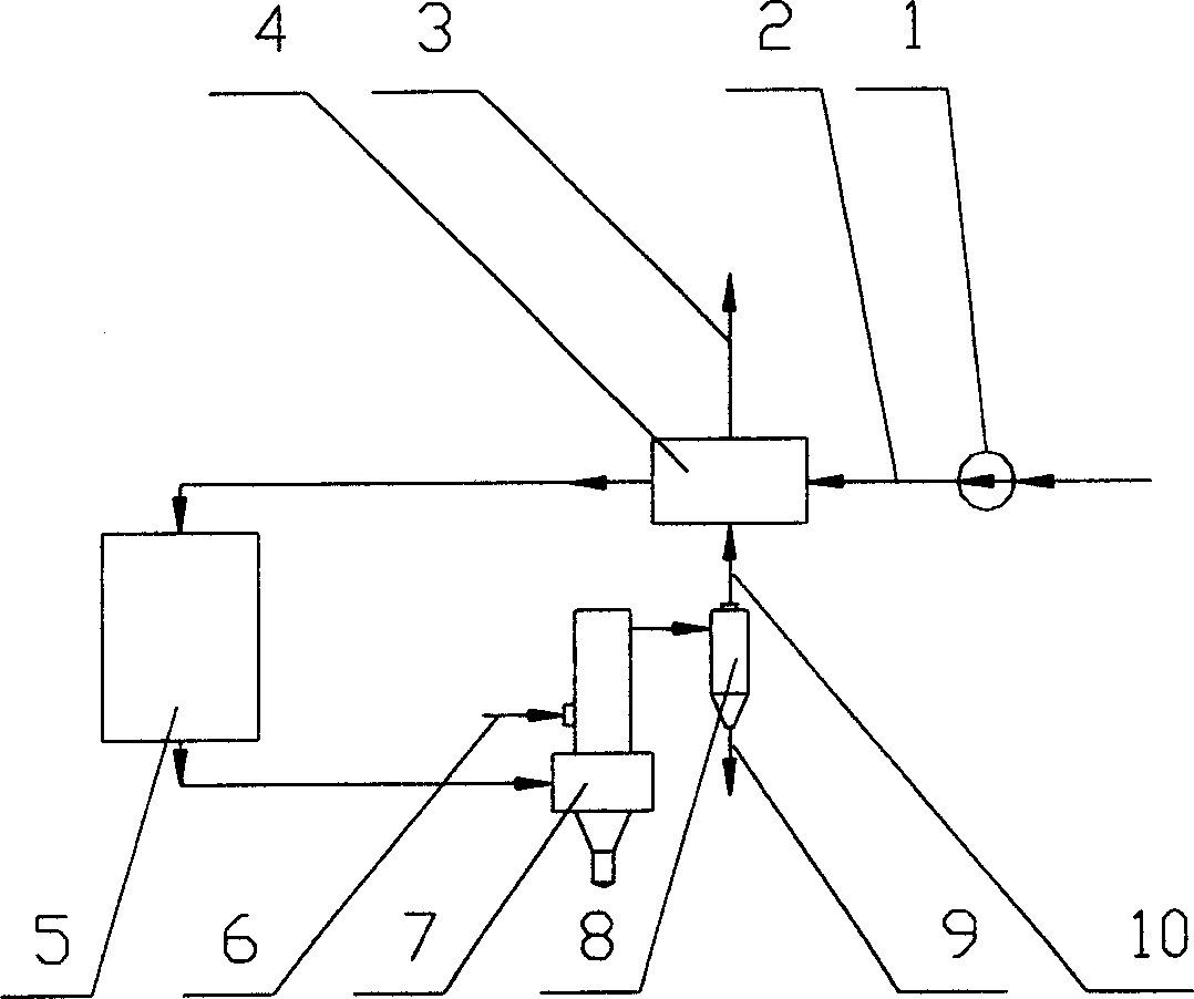
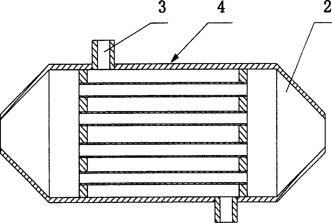
[0014] A drying device for implementing the above superheated steam drying method, consisting of a shell-and-tube heat exchanger 4, a heater 5, a closed direct dryer 7 and a vapor-solid separator 8, the tubes of the shell-and-tube heat exchanger 4 The channel inlet 2 is connected to the outlet of the water pump 1, and the tube side outlet is connected to the inlet of the heater 5, and the outlet of the heater 5 is connected to the inlet of the closed direct dryer 7, and the closed direct dryer 7 is equipped with wet sludge to add Port 6, the outlet of the closed direct dryer 7 is connected to the inlet of the vapor-solid separator 8 , and the dry tail gas outlet 10 of the vapor-solid separator 8 is connected to the shell side of the shell-and-tube heat exchanger 4 .

[0015] Working process of the present invention is as follows:

[0016] After the water is pressurized by the water pump 1, it enters the shell-and-tube heat exchanger 4 from the tube side inlet 2. After absorbin...


PUM


Abstract

The present invention relates to a sludge drying method, said method utilizes the sensible heat and latent heat of dried tail gas recovered by heat exchanger, and makes it exchange with water and heats it to obtain superheated steam, then makes the superheated steam by fed into a closed direct drying machine to make heat exchange with wet sludge being in said drying machine to obtain the dried sludge. Then said method can make the dried sludge and dried tail gas implement gas-solid separation, so that the dried sludge can be collected. Said drying equipment includes pipe-shell type heat exchanger, heater, closed direct drying machine and gas-solid separator, etc.

Description

technical field [0001] The invention relates to a sludge drying method and equipment, in particular to a sludge drying method and a drying device using superheated steam as a drying medium. Background technique [0002] At present, most of the sludge drying methods are direct drying and indirect drying. The drying medium of direct drying is usually the hot flue gas produced by fuel or waste combustion. The advantage is that the process flow is simple and the processing capacity of a single machine is large. Odor-causing substances must be deodorized before they can be discharged, and the heat loss of the drying tail gas is also very large, resulting in poor economic efficiency of the drying process. Indirect drying, the heat required for drying is transferred to the sludge through heat conduction, instead of using drying medium, the advantage is that there is no danger of explosion and fire, the amount of tail gas produced by drying is small, ...

Claims


Application Information

Patent Timeline
Patent Type & Authority Applications(China)
IPC IPC(8): C02F11/12
Inventor 葛仕福鲁维加郭宏伟
Owner JIANGSU TIANYING ENVIRONMENTAL PROTECTION ENERGY COMPLETE EQUIP CO LTD
Why Eureka
Try Eureka