

Luminescent material, and organic electro photoluminescence module wing same
A technology of luminescent materials and electroluminescence, which is applied in the direction of luminescent materials, electroluminescent light sources, electrical components, etc., can solve the problems of long purification time, difficult sublimation, poor thermal stability, etc.
- Summary
- Abstract
- Description
- Claims
- Application Information
AI Technical Summary
Problems solved by technology
Method used
Image

Examples
Embodiment 1
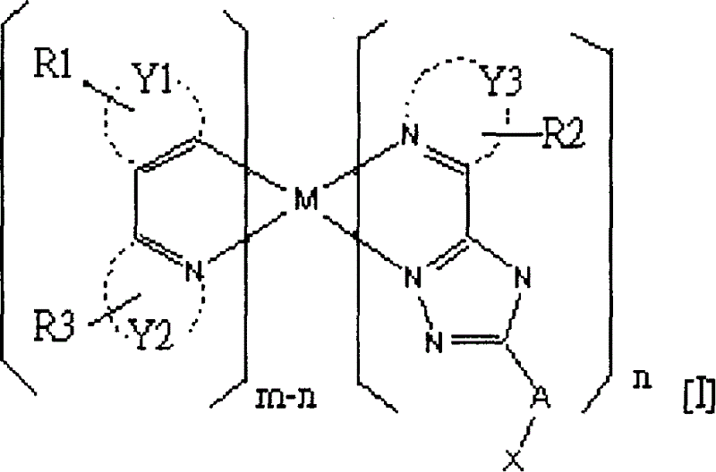
[0029] The present invention particularly provides a luminescent material, which has the properties of easy sublimation, thermal stability and rapid reaction, so the purification time is shorter than that of the traditional FIrpic blue phosphorescent material. Moreover, the components prepared by using the luminescent material of the present invention can obtain higher luminous efficiency and lower CIE value than the components prepared by the traditional application of FIrpic blue phosphorescent materials. Components made of phosphorescent materials are more biased toward blue light. Wherein, the luminescent material provided by the present invention is represented by chemical formula [I]:
[0030]
[0031] Wherein, "M" is a metal atom with an atomic number greater than 40, m is the number of ligands less than or equal to "M", and n is a positive integer less than m. "Y1" is selected from an aryl group or a heteroaryl group, and "Y2" and "Y3" are independently selected fr...
Embodiment 2
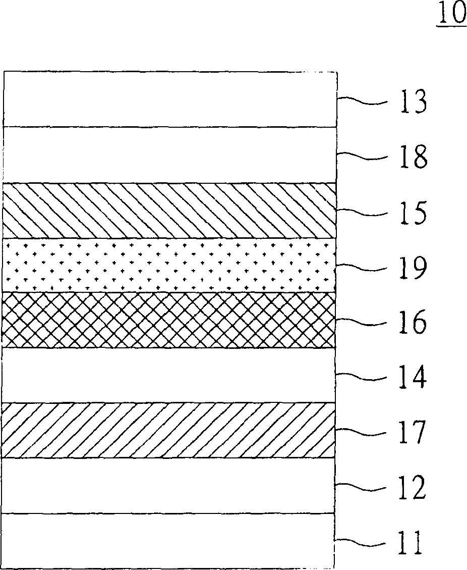
[0080] Please refer to figure 1 , which shows a schematic structural diagram of an organic electroluminescent device (OELD) according to Embodiment 2 of the present invention. In this embodiment, the organic electroluminescence component includes a small molecule organic light emitting diode (OLED) and a polymer light emitting diode (polymer light emitting diode, PLED). The OLED is used as an example for illustration, but the disclosed The technology can also be applied to PLEDs.
[0081] exist figure 1 Among them, the organic electroluminescent device 10 includes a substrate 11 , an anode 12 , a cathode 13 , a hole transport layer 14 , an electron transport layer 15 and a light emitting layer 16 . The anode 12 and the cathode 13 are disposed on the substrate 11 , the hole transport layer 14 is disposed between the anode 12 and the cathode 13 , and the electron transport layer 15 is disposed between the hole transport layer 14 and the cathode 13 . The light-emitting layer 1...
Embodiment 3
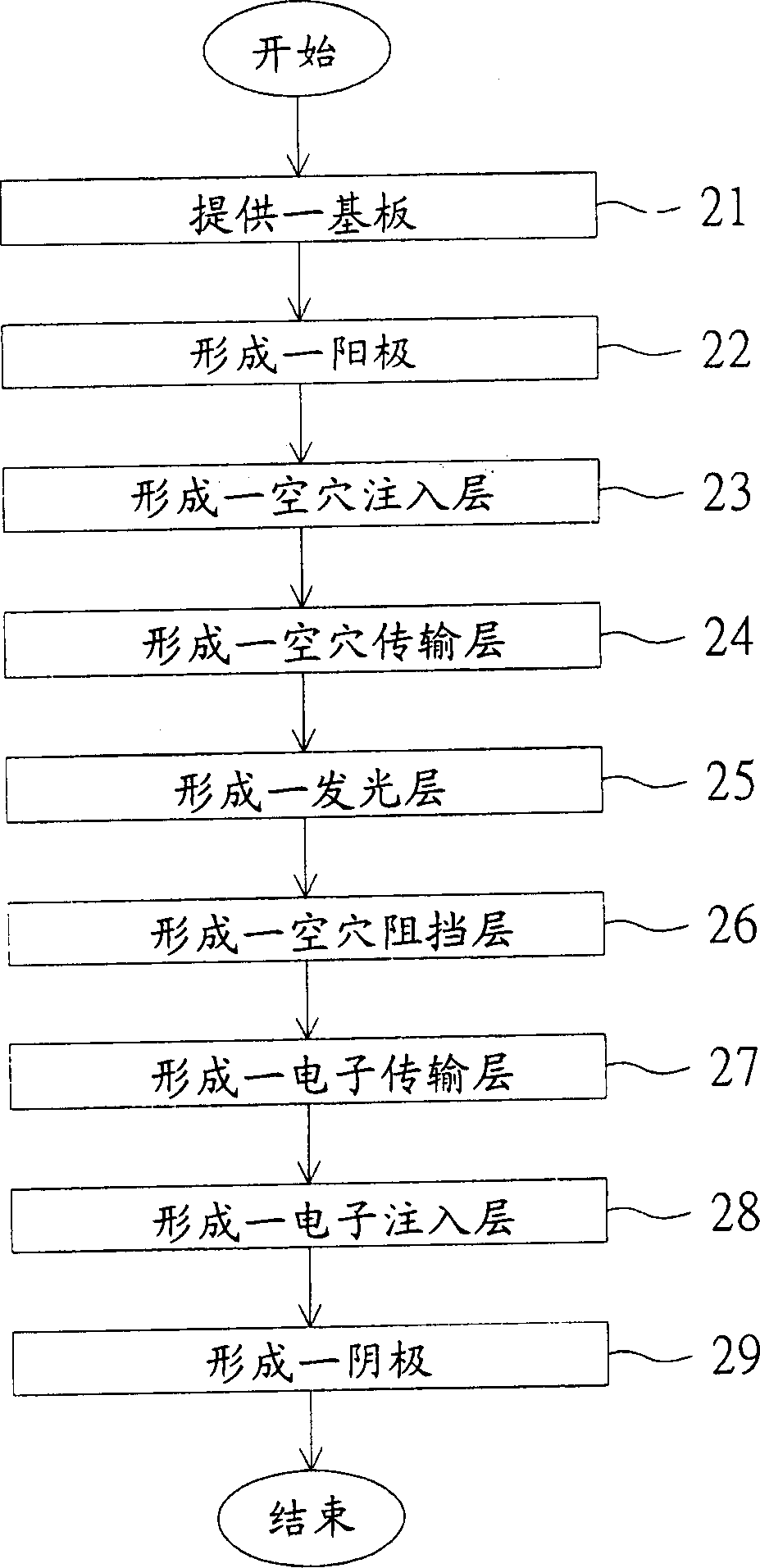
[0101] refer to figure 2 , which shows a flow chart of a method for manufacturing an organic electroluminescence component according to Embodiment 3 of the present invention. Also refer to figure 1 , firstly, in step 21, a substrate 11 is provided. Then, enter step 22 , form an anode 1 on the substrate 11 . Then, enter step 23 , forming a hole injection layer 17 on the anode 12 . Next, enter step 24 , forming a hole transport layer 14 on the hole injection layer 17 . Then, enter step 25, form a light-emitting layer 16 on the hole transport layer 14, light-emitting layer 16 is made of a host light emitter and a guest light emitter, the guest light emitter is represented by the above-mentioned chemical formula [I]. Next, enter step 26 , forming a hole blocking layer 19 on the light emitting layer 16 . Then, enter step 27 , forming an electron transport layer 15 on the hole blocking layer 19 . Next, enter step 28 , forming an electron injection layer 18 on the electron tra...
PUM
| Property | Measurement | Unit |
|---|---|---|
| Luminous efficiency | aaaaa | aaaaa |
| Luminous efficiency | aaaaa | aaaaa |
Abstract
Description
Claims
Application Information