

Current measurement method, electronic type current transformer utilized, and new application of the current transformer
A current transformer and current measurement technology, applied in the direction of measuring electricity, measuring electrical variables, measuring current/voltage, etc., to achieve the effect of large dynamic range, high measurement accuracy and small size
- Summary
- Abstract
- Description
- Claims
- Application Information
AI Technical Summary
Problems solved by technology
Method used
Image

Examples
Embodiment Construction
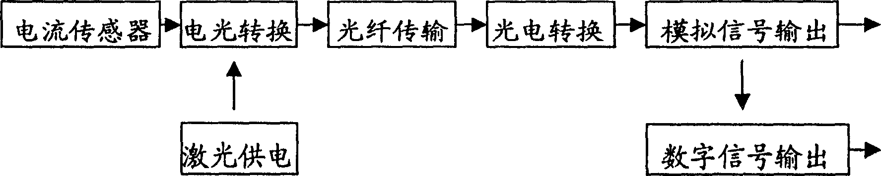
[0045] see figure 1 , a current measurement method, is to use the current magnetic field sensing head which is closely combined with the power transmission bus, which is composed of a strong magnetostrictive amorphous alloy sheet and a piezoelectric ceramic, and the linear magnetic field generated by the current flowing through the power transmission bus It becomes a voltage analog signal and transmits the voltage analog signal to the electro-optical conversion device; the electro-optic conversion device converts the voltage analog signal into an analog optical signal, and then sends the analog optical signal to the ground potential side through an optical fiber; on the ground potential side, by The photoelectric conversion device converts the analog optical signal into an analog electrical signal for output. At the same time, the analog electrical signal output by the photoelectric conversion device can be converted into a digital signal by A / D for user selection. Users can ...
PUM
 Abstract
Description
Claims
Application Information