
Pulse modulation type three-dimensional image-forming method and system containing no scanning device

A technology of pulse modulation and three-dimensional imaging, which is applied in radio wave measurement systems, instruments, electromagnetic wave re-radiation, etc., can solve the problem of incompatibility between distance measurement accuracy and spatial resolution, two-dimensional images are not enough to fully express information, and spatial resolution Low efficiency and other problems, to achieve the effect of strong anti-background light interference, low stability requirements, and simple modulation

Inactive Publication Date: 2005-11-23
ZHEJIANG UNIV
View PDF0 Cites 20 Cited by
  • Summary
  • Abstract
  • Description
  • Claims
  • Application Information

AI Technical Summary

Problems solved by technology

Two-dimensional imaging technologies are relatively mature, but they can only obtain two-dimensional image information, and the real world is a three-dimensional space, and two-dimensional images are not enough to fully express all information
Because the imaging distance of this method is relatively long, but under the condition of a CCD array with a certain pixel rate, the distance resolution (series) is inversely proportional to the spatial resolution, so the distance measurement accuracy and spatial resolution cannot be achieved at the same time.
In addition, research institutions such as the Lincoln Laboratory of the United States and the Swiss Electronics and Microtechnology Research Center are developing a scanner-free 3D imaging technology based on an integrated circuit with a high-speed optical pulse response. This method can detect a long distance, but its ranging accuracy is slightly low at present. , with a lower spatial resolution

Method used


Image

  • Pulse modulation type three-dimensional image-forming method and system containing no scanning device
  • Pulse modulation type three-dimensional image-forming method and system containing no scanning device
  • Pulse modulation type three-dimensional image-forming method and system containing no scanning device

Examples


Embodiment Construction

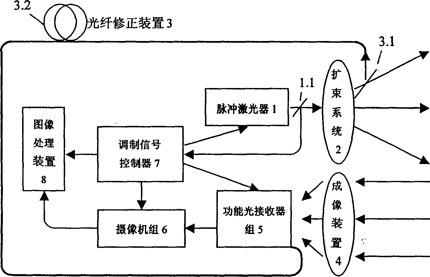
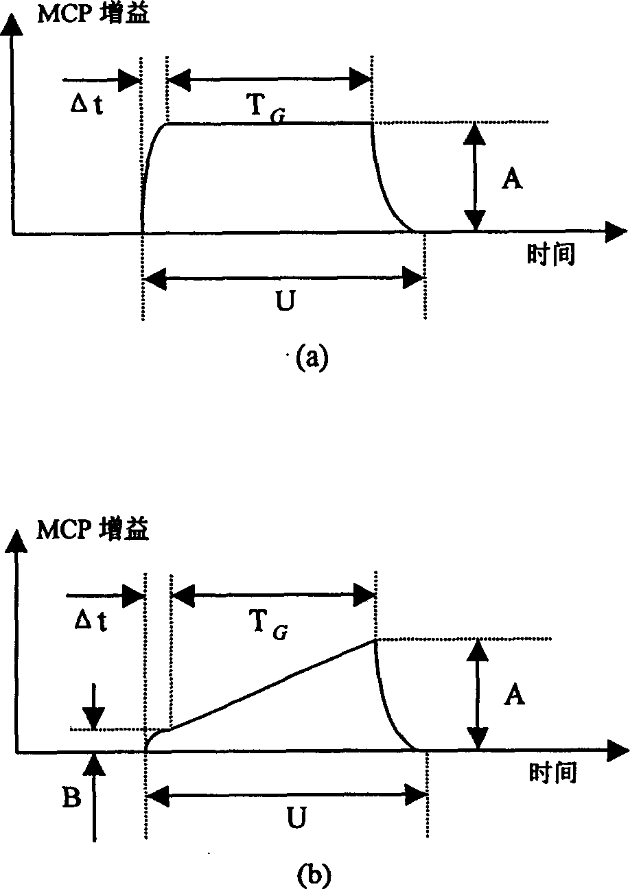
[0014] Scannerless pulse-modulated three-dimensional imaging method: using a pulsed laser light source, the light pulse illuminates the target through the beam expander system and is received by the optical imaging system and imaged on the receiving surface of the controlled functional optical receiver group. The output optical signal of the optical receiver group, for the same scene, under the condition that the light pulse illumination of different intensities or the gain of the functional optical receiver is a function of different time variables, two or more intensity images are obtained. At the output end, a beam splitting device is used to split part of the light energy and measure it, and the measured value is used as the corrected light intensity value; the image processing module is used to analyze the light intensity value and the corrected light intensity value of each pixel in the collected image series Carry out calculation processing, calculate the distance of eac...


PUM


Abstract

The invention relates to a method and system of non-scanner impulse modulating three-space imagery. Impulse laser emits optical pulsing light testing scene; reflected light is inputted into receiver through image system and its output is connected with video camera set; the output of video camera set is connected with image handling device; one of modulating signal controller controls impulse laser or probing laser impulse; while another one controls functional light receiver set and video camera set and transmits the signal to image handling device at the same time. The gain of functional light receiver is time variable function. It uses intensity image of at least two laser impulses light with different intensity or the gains of functional receiver as different time variable function, then generates three-space imagery by computing. The range-measuring system doesn't have scan parts.

Description

technical field [0001] The invention relates to the field of three-dimensional imaging or imaging ranging, in particular to a scanner-less pulse modulation three-dimensional imaging method and system. Background technique [0002] Ranging technology With the continuous progress and development of human society and science and technology, people have higher and higher requirements for information acquisition. Two-dimensional imaging technologies are relatively mature, but they can only obtain two-dimensional image information, and the real world is a three-dimensional space, and two-dimensional images are not enough to fully express all information. Three-dimensional imaging display technology will greatly promote the development of related detection, simulation and entertainment. Among the 3D imaging systems, optical 3D imaging has the highest resolution. However, traditional optical three-dimensional imaging systems, such as traditional laser imaging radars, require mecha...

Claims


Application Information

Patent Timeline
Patent Type & Authority Applications(China)
IPC IPC(8): G01S17/08
Inventor 张秀达严惠民
Owner ZHEJIANG UNIV
Learn More