
Method for rapidly sintering Nd-Fe-B ferromagnet

A rapid sintering, NdFeB technology, applied in the manufacture of inductors/transformers/magnets, circuits, electrical components, etc., can solve the problems of reduced magnet performance, low magnetic performance, shortening, etc., to achieve shortened sintering time, low sintering temperature, The effect of short manufacturing cycle

Inactive Publication Date: 2005-11-30
SICHUAN UNIV
View PDF0 Cites 6 Cited by
  • Summary
  • Abstract
  • Description
  • Claims
  • Application Information

AI Technical Summary

Problems solved by technology

However, when the sintering temperature is lower than 780 ° C, the pressure is small, and the holding time is less than 10 minutes, denser sintered NdFeB magnets cannot be obtained.
Since the SPS technology uses the instantaneous high-temperature field generated by pulse energy, discharge pulse pressure and Joule heat to realize the sintering process, it greatly shortens the heating time and sintering time compared with the traditional process of preparing sintered NdFeB magnets, and reduces Sintering temperature, but because the heating time of SPS technology is limited by the plasma generated between the magnetic powders during sintering, it cannot be greatly shortened; at the same time, when the sintering temperature and sintering time are continued to be reduced, dense sintered NdFeB magnets will not be obtained ; Moreover, the use of SPS technology for sintering requires a low density of the green body, generally below 50%, otherwise, too dense a green body is not conducive to the generation of plasma under the action of current, and it cannot generate high temperature
In addition, since SPS sintering is a system pressure sintering method, during the sintering process, on the one hand, the system needs to provide a strong external pressure to make the sintered compact, so as to improve the magnetic properties of the sintered NdFeB magnet; The huge pressure applied will inevitably seriously reduce the degree of orientation of the magnet, which will greatly reduce the performance of the magnet.
Therefore, when SPS technology is used for sintering, there is always a contradiction between increasing the density of magnets and reducing the magnetic properties of magnets, which also leads to the problem that the magnetic properties of sintered NdFeB magnets prepared by SPS method are all low.

Method used


Image

  • Method for rapidly sintering Nd-Fe-B ferromagnet
  • Method for rapidly sintering Nd-Fe-B ferromagnet
  • Method for rapidly sintering Nd-Fe-B ferromagnet

Examples


Embodiment 1~19

[0021] 1. Calculate the composition as Nd in atomic percentage 15 Fe 78.3 B 6.7 、Nd 13.8 Fe 80 B 6.2 and Nd 12.4 Fe 81.6 B 6.0 Under the protection of Ar gas, the NdFeB alloys are respectively melted in the vacuum melting furnace according to the conventional process conditions, and then the melted ingots are roughly crushed by hydrogen explosion and ball milled into 3-5μm NdFeB alloy fine powder, and put into the mold , after being oriented by a magnetic field, press the relative density listed in the table to form a cylindrical compact with a diameter of 13mm and a height of 6mm (for comparison);

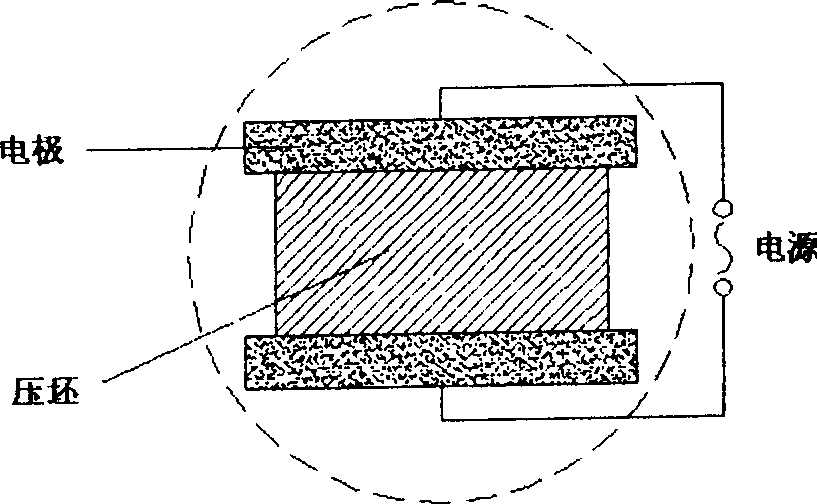
[0022] 2. Press figure 1 As shown, after the prepared green compact is fixed with the chuck, in 10 -3 Under the vacuum condition of Pa, adjust the current of the control system according to the corresponding heating and temperature rise rates of each embodiment determined in the table, and use the current to pass through the compact to make it rapidly heated. When a cert...


PUM


Abstract

This invention discloses one method to Nd boron magnetism method by use of field rapid sintering, which comprises the following steps: vacuum melting the alloy with Nd 12.4-15.5, Fe 77.7-81.4, B 6.0-6.8 and then grinding into powder of Nd boron alloy powder of 3-5mu m to be filled into model and pressing into block after field direction; then putting the block into the melting device with output voltage of three to ten volt and output current of 800-5000 ampere under vacuum conditions of 10-3Pa; using current to rapidly heating the block under temperature of 500-900DEG C for five to eight minutes to fulfill the process.

Description

1. Technical field [0001] The invention belongs to the technical field of sintering NdFeB magnets, and in particular relates to a method for rapidly sintering NdFeB magnets at low temperature using an electric field. 2. Background technology [0002] At present, the vast majority of neodymium iron boron (NdFeB) magnets are made by traditional powder metallurgy. The process of this method is as follows: the smelted NdFeB alloy ingot is broken into fine powder of 3-5 μm, pressed into a green body with a relative density of 50-70% in a magnetic field, and then sintered at a temperature of Sintering is carried out in a vacuum sintering furnace at about 1050°C to 1120°C. The specific sintering temperature is related to the content of Nd in the NdFeB alloy. The lower the Nd content, the higher the sintering temperature, and when the green body is heated from room temperature to the sintering temperature in this method, the heating time takes about 2 hours, and the sintering time...

Claims


Application Information

Patent Timeline
Patent Type & Authority Applications(China)
IPC IPC(8): H01F41/02
Inventor 杨屹冯可芹杨刚刘颖涂铭旌
Owner SICHUAN UNIV
Learn More