Directional freeze method for TiAl-based alloy plate

A technology of directional solidification and directional solidification furnace, which is applied in the field of continuous casting directional solidification, and can solve problems such as unsuitable plate processing and unsuitable TiAl-based alloy material processing.

Inactive Publication Date: 2006-02-15
HARBIN INST OF TECH
View PDF1 Cites 20 Cited by
  • Summary
  • Abstract
  • Description
  • Claims
  • Application Information

AI Technical Summary

Problems solved by technology

[0003] In view of the fact that the existing directional solidification method is not suitable for the processing of plates, and at the same time the existing directional solidification method is not suitable for the processing of TiAl-based alloy materials, the present invention provides a capacitive electromagnetic melting and constrained forming method that can obtain ingots with excellent performance A method for directional solidification of a TiAl-based alloy plate integrated with directional solidification, in which a cold crucible 5 with the functions of constraining molten alloy and controlling the distribution of a magnetic field is installed in the electromagnetic constrained forming and directional solidification furnace 7 with functions of electromagnetic constrained forming and directional solidification, The cross section of the cavity 5-1-1 of the cold crucible 5 is rectangular, and an induction coil 6 with 2 to 8 turns is fixed outside the cold crucible 5, and an upper end and a The dummy ingot 4 fixedly con

Method used


Image

  • Directional freeze method for TiAl-based alloy plate
  • Directional freeze method for TiAl-based alloy plate
  • Directional freeze method for TiAl-based alloy plate

Examples


specific Embodiment approach 1

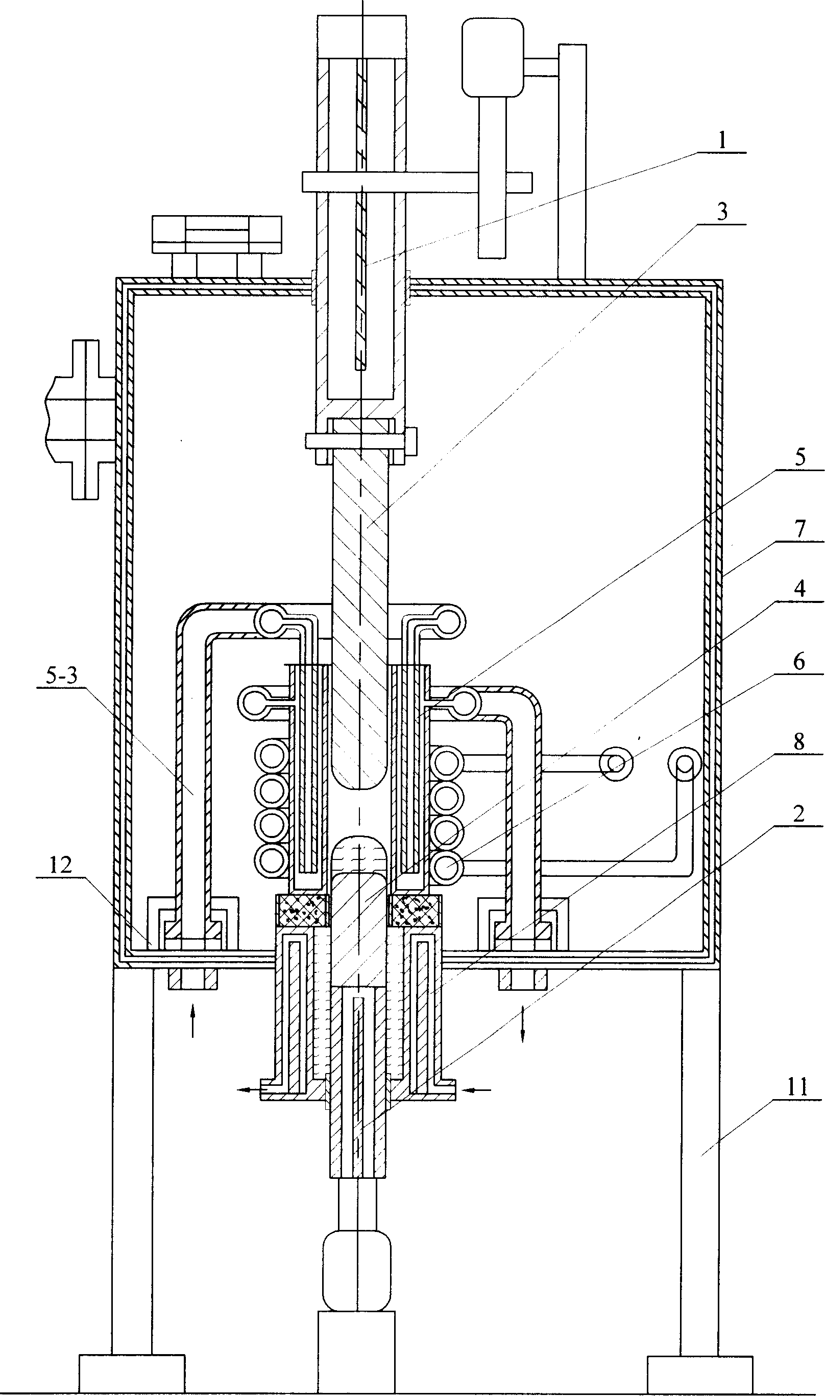
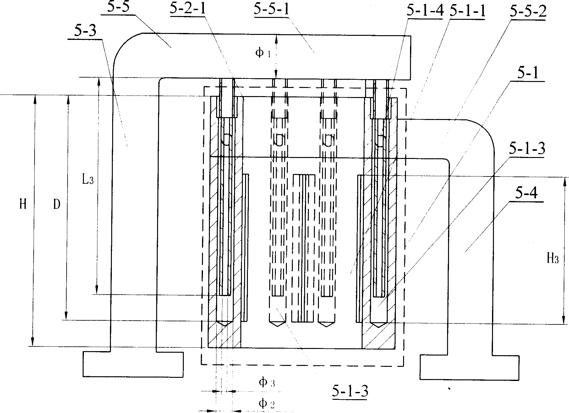
[0005] Specific embodiment one: the directional solidification method of the TiAl-based alloy sheet in this embodiment is to install a furnace 7 with the functions of constraining molten alloy and controlling the distribution of magnetic field in the electromagnetic constrained forming and directional solidification furnace 7 with the functions of electromagnetic constrained forming and directional solidification Cold crucible 5, the cross section of the cavity 5-1-1 of the cold crucible 5 is rectangular, 2 to 8 turns of induction coil 6 are fixed outside the cold crucible 5, and then in the cavity 5-1-1 of the cold crucible 5 A dummy ingot 4 whose upper end is fixedly connected to the upper feeding mechanism 1 and a TiAl-based alloy material rod 3 whose lower end is fixedly connected to the lower drawing mechanism 2 are provided. The TiAl-based alloy material rod 3 is arranged directly above the dummy ingot 4, and the The ratio of the width W, length L, and height H of the cha...

specific Embodiment approach 2

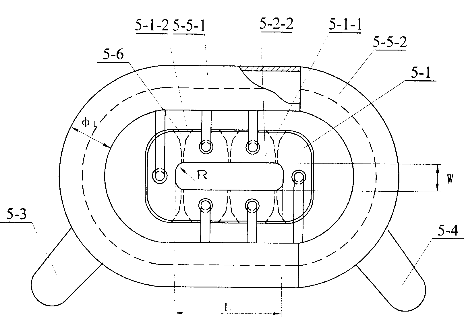
[0015] Specific embodiment two: the structure of the slits 5-6 that can ensure the uniform distribution of the magnetic field in the crucible is six straight slits, or four oblique slits and two straight slits, or four oblique slits slits and four straight slits, filling the slits with low-conductivity materials to electrically insulate both ends of the slits; the cross-sectional shape of any of the slits 5-6 is: two widths W near the inside of the crucible 1 It is a parallel straight line 5-6-1 of 0.1 ~ 0.5mm, and its radially outward length L 1 2-4 mm, the parallel straight line 5-6-1 transitions to the outer surface 5-1-2 of the crucible body 5-1 through the straight line 5-6-2 or arc 5-6-3. It has been proved by experiments that the position and structure of the slits can well ensure the uniform distribution of the magnetic field in the crucible, so that the melting temperature of each position of the metal is consistent, so as to better realize the electromagnetic confine...

specific Embodiment approach 3

[0016] Specific Embodiment Three: The coil 6 in this embodiment is a single coil, the coil 6 in this embodiment is connected to a single-phase power supply with a power of 75-90kW, and the width W, length L, and height H of the cavity 5-1-1 are The ratio between them is 1:2.2-3.2:10-15, and under the same conditions as those in Embodiment 1, a rectangular blank with an aspect ratio of 2-3 can be obtained. Control the power of the single-phase power supply within this range, so that the upper feeding material can be fully melted and a certain degree of superheat can be maintained. When the ingot moves downward and is constrained to form, it has sufficient binding force to ensure the integrity of the ingot shape and obtain orientation. For the solidification structure, since the aspect ratio of the cast ingot is required to be small in this embodiment, there is no need to use the heat preservation jacket 10, see FIG. 13 .


PUM


Abstract

The continual casting directional solidification method for TiAl-base alloy plate comprises, putting TiAl alloy material bar 3 and dummy ingot 4 with rectangular intersection into the electromagnetic induction range of coil 6, galvanizing to coil 6 with single-phase alternating current with power of 75~100kW from electrical power for 20~25min; the alloy bar 3 and ingot 4 move downward with velocity of 0.01-0.05mm/min and get into the bottom crystallizer 8. This invention overcomes the limit to rectangular intersection blank and fits to press for high performance material in economy, science and national defense industry.

Description

Technical field: [0001] The invention relates to a continuous melting and casting directional solidification method. Background technique: [0002] The existing methods for directional solidification of TiAl-based alloys are combined with a circular cavity for melting and casting processing. Since the magnetic induction intensity distribution and metal melting temperature of the cold crucible of the circular cavity are relatively consistent in all directions, so The process conditions that need to be considered are relatively simple, but for relatively complex rectangular cross-section plates, melting and casting cannot be achieved through the existing melting and casting methods, because the directional solidification of the cold crucible is first faced with the heating and melting of the alloy and the electromagnetic force For the constrained forming problem, for electromagnetic melting and constrained forming in a cold crucible with a rectangular cross-section, compared w...

Claims


Application Information

Patent Timeline
IPC IPC(8): B22D11/115
Inventor 丁宏升王艳丽李春晖毕维生郭景杰傅恒志
Owner HARBIN INST OF TECH
Why Eureka
Try Eureka