Column for ion chromatograph, suppressor and ion chromatograph

A technology for ion chromatography and separation column, which is applied in the field of ion chromatography columns, suppressors and ion chromatography, and can solve the problems of undisclosed ion chromatography suppressor, failure to meet the performance of component parts, and undisclosed porous ion exchange agent and other issues

Inactive Publication Date: 2006-03-08
ORGANO CORP
View PDF6 Cites 16 Cited by
  • Summary
  • Abstract
  • Description
  • Claims
  • Application Information

AI Technical Summary

Problems solved by technology

[0022] In addition, as mentioned above, for the separation column, the concentration column and the suppressor, the purpose of each setting is different, and the required performance is also different. Only introducing ion exchange groups into the organic porous body cannot meet the requirements of the respective components. required performance
In addition, Patent Documents 1 to 3 do not disclose suppressors for ion chromatography, and Patent Document 4 does not disclose the use of porous ion exchangers for ion chromatography.

Method used


Image

  • Column for ion chromatograph, suppressor and ion chromatograph
  • Column for ion chromatograph, suppressor and ion chromatograph
  • Column for ion chromatograph, suppressor and ion chromatograph

Examples


Embodiment 1

[0068] (production of suppressor)

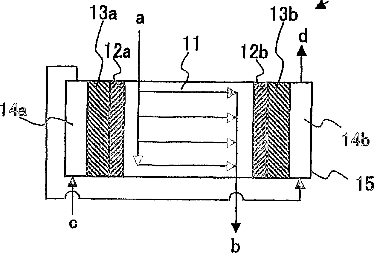
[0069] The above-mentioned organic porous cation exchanger A was cut into a cylindrical shape, and filled in a cylindrical column with an inner diameter of 3 mm so that the length of the packed layer was 10 mm. Nafion 117 (manufactured by Dupont Corporation) as a cation exchange membrane is closely attached to both ends of a horizontal columnar organic porous cation exchanger, and a platinum mesh is provided at both ends of the outer side so as to be in contact with the ion exchange membrane. electrodes, formed in accordance with figure 2 In the way of the flow path shown, a liquid flow nozzle for the effluent from the separation column is installed at this part, and a tube for liquid flow with the electrode chamber is installed, and the production is as follows: figure 2 A suppressor constructed like that.

[0070] (Manufacture of organic porous body B)

[0071] An organic porous body B was produced in the same manner as that of the or...

Embodiment 2

[0078] Embodiment 2 (making of separation column)

[0079] The above-mentioned organic porous anion exchanger B was cut and filled in a column with an inner diameter of 4.0 mm and a length of 150 mm. At a liquid flow rate of 1ml / min, pass through 0.5N sodium hydroxide aqueous solution for 20 minutes, then pass pure water at a rate of 1ml / min, carry out water washing for 30 minutes, and form an anion exchanger in the form of OH, Then, a 1:1 mixed aqueous solution of 3.5 mM sodium carbonate and 0.4 mM sodium bicarbonate was passed through at 1.5 ml / min for 20 minutes to equilibrate it to obtain a separation column. Equilibrium treatment was carried out in a constant temperature bath at 35°C. The fluid flow pressure at the end of the equalization treatment was 0.45 MPa.

Embodiment 3

[0080] Embodiment 3 (making of concentrating column)

[0081] The above-mentioned organic porous ion exchanger C was cut and filled in a column with an inner diameter of 3.0 mm and a length of 10 mm. At a flow rate of 1ml / min, pass a 0.5N sodium hydroxide aqueous solution for 10 minutes, then wash with pure water at a rate of 1ml / min for 20 minutes to form the anion exchanger into an OH form, and then A 1:1 mixed aqueous solution of 3.5 mM sodium carbonate and 0.4 mM sodium bicarbonate was passed through at 2 ml / min for 20 minutes, and equilibrated to obtain a concentrated column. Equilibrium treatment was carried out in a constant temperature bath at 35°C. The fluid flow pressure at the end point of the equilibration treatment was 0.05 MPa.

[0082] (Performance Evaluation of Concentrator Column)

[0083] The concentration column obtained in the above manner is used for the concentration column, and the following column is used for the separation column, that is, in a colu...


PUM

PropertyMeasurementUnit
radiusaaaaaaaaaa
radiusaaaaaaaaaa

Abstract

A separation column for an ion chromatograph, which is packed with an organic porous ion exchanger having a three-dimensionally network structure which has an open cell cellular structure comprising macropores connected with each other and, being present in the wall between them, a mesopore having a radius of 0.01 to 50 mum, has a total pore volume of 1 to 50 ml / g, exhibits a value obtained by dividing the half width of the main peak of the pore distribution curve thereof by the radius of the peak top of the main peak of 0.5 or less, and has ion exchange groups introduced so as for the exchanger to have an ion-exchange capacity of 0.1 to 5000 mug equivalent / g-dry organic porous ion exchanger. The separation column exhibits high performance capability especially for the separation and concentration of low molecular weight ions, and thus can be used for passing a sample solution through it with a reduced pressure while retaining a high capability for ion resolution.

Description

technical field [0001] The present invention relates to an ion chromatograph column, a suppressor, and an ion chromatograph for quantitative analysis of ionic substances in liquids in the fields of water for power plants, water for precision processing and cleaning in semiconductor manufacturing, water for food processing, and environmental water quality analysis. instrument. Background technique [0002] An ion chromatograph combines various components to form a single device. Fig. 6 schematically shows an example of an ion chromatograph used in the past. The ion chromatograph 20 is composed of a sample solution box 21, a sample pump 23, an eluent box 22, an eluent pump 24, a concentration column 25, a separation column 26, a suppressor 27, a detector 28, valves e, f, and g , h, I and the pipes connecting these components, other guard columns not shown in the figure, valves, degassers, thermostats, data processing devices, etc. constitute. In order to quantitatively anal...

Claims


Application Information

Patent Timeline
Patent Type & Authority Applications(China)
IPC IPC(8): B01J20/281G01N30/60G01N30/02B01D15/08B01D15/36B01J20/285B01J39/26B01J41/20G01N30/08G01N30/46G01N30/52G01N30/88G01N30/96
CPCG01N2030/965B01J41/20B01J20/28054G01N2030/525G01N30/96B01J39/26B01J20/28088B01J20/28085B01J20/28083B01D15/361B01J20/282
Inventor 山中弘次井上洋吉田晃子藤田雅司
Owner ORGANO CORP
Why Eureka
Try Eureka