Continuous carbon fibre graphitizing method and apparatus
A technology of graphitization and carbon fiber, which is applied in the fields of fiber chemical characteristics, chemical post-treatment of rayon, textiles and papermaking, etc. It can solve the problems affecting the stability of graphitized fibers, inconvenient operation and control, and uneven heating of fibers, so as to avoid The effects of poor heating stability, light weight, and simple equipment
- Summary
- Abstract
- Description
- Claims
- Application Information
AI Technical Summary
Problems solved by technology
Method used
Image
Examples
Embodiment 1
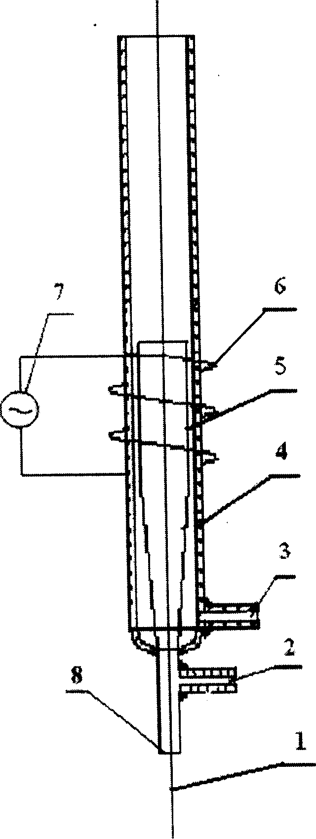
[0024] Using 3K carbon fiber as raw material, the fiber stays in the acetone solution for 3 minutes, and after being dried at 200°C for 3 minutes, it enters the plasma graphitization device 6, the frequency of the high-frequency generator is 27MHz, and the draft ratio of the fiber is -1 %, the flow of argon plasma gas 2 is 2L / min, the flow of cooling gas 3 is 15L / min, the residence time of fiber in the plasma torch is 15 seconds, the output frequency of adjusting high-frequency generator 3 is 2KW, the sizing agent The concentration is 2%, the residence time is 20 seconds, and finally dried at 200° C. for 3 minutes to obtain graphite fibers. The properties are shown in Table 1.
Embodiment 2
[0026] Using 3K carbon fiber as raw material, the fiber stays in the acetone solution for 5 minutes, and after being dried at 300°C for 1 minute, it enters the plasma graphitization device 6, the frequency of the high-frequency generator is 27MHz, and the flow rate of the argon plasma gas 2 is 2L / min, the flow rate of cooling air 3 is 15L / min, the residence time of fiber in plasma torch is 15 seconds, the draft ratio of fiber is 1%, the output frequency of adjusting high-frequency generator 3 is 2.5KW, the sizing agent The concentration is 5%, the residence time is 20 seconds, and finally dried at 200° C. for 3 minutes to obtain graphite fibers. The properties are shown in Table 1.
Embodiment 3
[0028] Using 3K carbon fiber as raw material, the fiber stays in the acetone solution for 10 minutes, and after being dried at 300°C for 1 minute, it enters the plasma graphitization device 6. The frequency of the high-frequency generator is 27MHz, and the draft ratio of the fiber is 2%. , the flow rate of the argon plasma gas 2 is 2L / min, the flow rate of the cooling gas 3 is 15L / min, the residence time of the fiber in the plasma torch is 15 seconds, the output frequency of the high-frequency generator 3 is adjusted to be 3KW, and then the sizing is carried out. The concentration of the sizing agent is 2%, the residence time is 120 seconds, and finally dried at 300° C. for 1 minute to obtain graphite fibers.
[0029] The properties are shown in Table 1.
PUM
 Abstract
Description
Claims
Application Information
 - R&D
- Intellectual Property
- Life Sciences
- Materials
- Tech Scout
- Unparalleled Data Quality
- Higher Quality Content
- 60% Fewer Hallucinations
Browse by: Latest US Patents, China's latest patents, Technical Efficacy Thesaurus, Application Domain, Technology Topic, Popular Technical Reports.
© 2025 PatSnap. All rights reserved.Legal|Privacy policy|Modern Slavery Act Transparency Statement|Sitemap|About US| Contact US: help@patsnap.com

