
Integrated high temperature high efficiency soundwave and blower and its producing method

A sonic soot blower and high-temperature-resistant technology, which is applied in the direction of combustion methods, manufacturing tools, and removal of solid residues, etc., can solve the problems of affecting the airflow injection power, poor fluid distribution transition, and complex cavity shape, etc., to achieve uniform and smooth flow of airflow , prolong the service life and improve the practical effect

Inactive Publication Date: 2006-03-22
薛铁山
View PDF0 Cites 8 Cited by
  • Summary
  • Abstract
  • Description
  • Claims
  • Application Information

AI Technical Summary

Problems solved by technology

However, in the manufacture of soot blowers, due to the complex shape of the inner cavity of the soot blower and the difficulty in manufacturing, most of them use machined assembly weldments, and the materials used must be ordinary heat-resistant steel with machinability. However, the high temperature resistance of these ordinary heat-resistant steels is about 900°C, and the maximum temperature in the boiler furnace is 1300°C, which causes the high temperature resistance of the selected materials to be inconsistent with the actual temperature in the boiler.
Therefore, in order to avoid burning and damaging the soot blower, the installed soot blower must avoid the high-temperature zone of the boiler during installation, and can only be installed in or outside the furnace wall. , it is necessary to install a large casing on the furnace wall to support the soot blower, and the gas can only be blown in a straight line from the casing of the pipe wall, resulting in unsatisfactory effects of dust removal, descaling, and decoking
In addition, the processing surfaces of the gas flow distribution cavity and the return cavity of the soot blower are straight and conical, so that the gas is easy to form a dead angle when it flows, resulting in poor fluid distribution transition and affecting the power of the air jet.
Moreover, the existing sootblowers generally only have two blowing angles, that is, forward blowing and back blowing. Because the target is not strong, it is difficult to achieve the ideal effects of dust removal, descaling and decoking

Method used

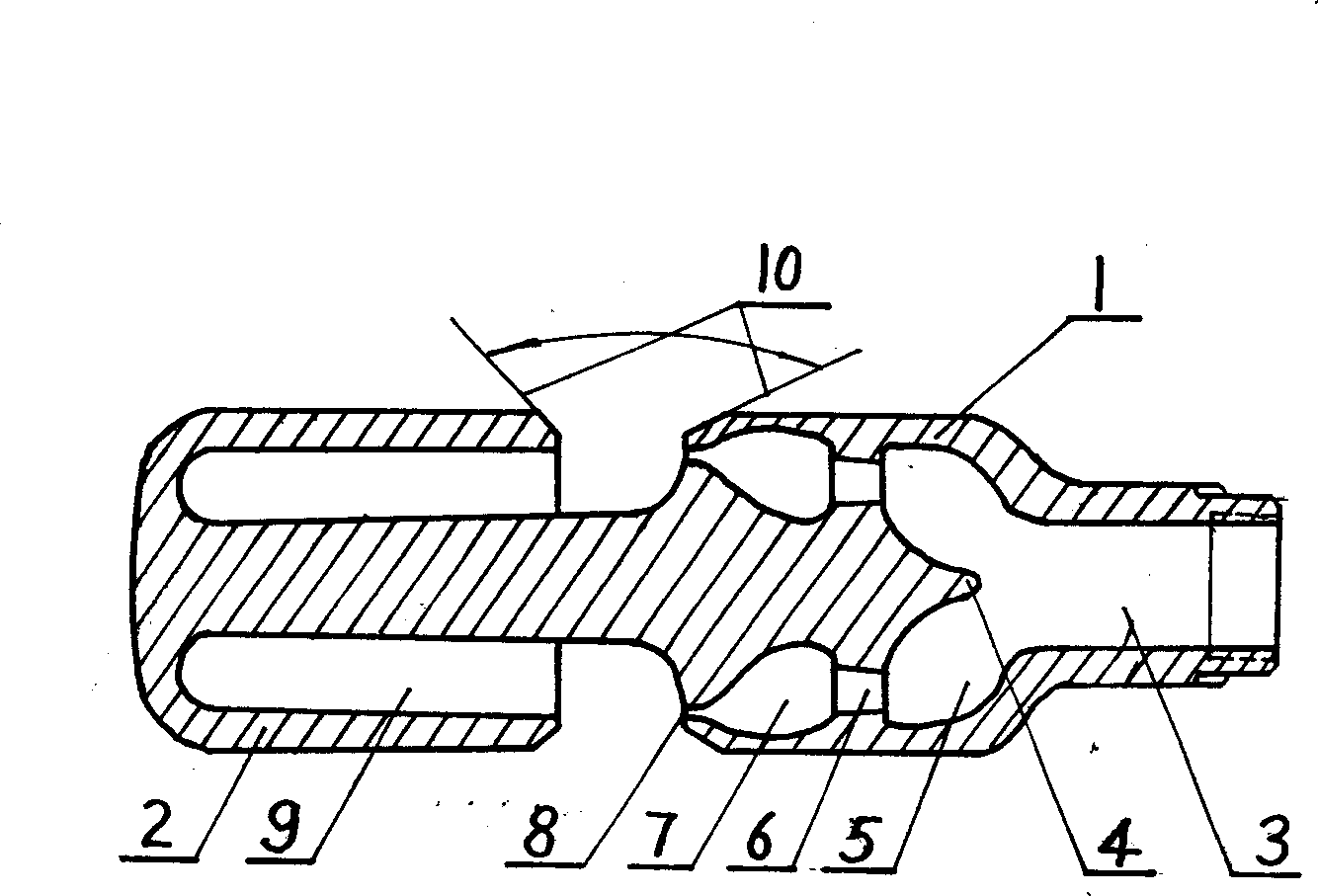
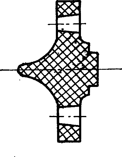
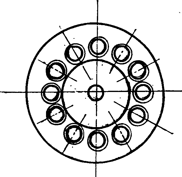

Image

  • Integrated high temperature high efficiency soundwave and blower and its producing method
  • Integrated high temperature high efficiency soundwave and blower and its producing method
  • Integrated high temperature high efficiency soundwave and blower and its producing method

Examples


Embodiment Construction

[0024] See figure 1 , The integrated high-temperature-resistant and high-efficiency boiler sonic sootblower of the present invention is composed of an air flow cavity 1 and a return cavity 2 that are connected as a whole, wherein the inlet end 3 of the air flow cavity 1 is directly connected with the inlet pipe, and the outlet end It is connected to the reflux cavity 2, and the other end of the reflux cavity 2 is a blind end. The transition surfaces of the outer walls of the two cavities and the airflow chamber are geometrically rounded arc surfaces, and the cavity of the airflow cavity 1 has a rounded arc surface. The first-level air distribution chamber 5 and the second-level air injection chamber 7 communicate with each other through a split hole 6. The split hole 6 is a tapered hole or a horn hole. 8 to 14 can be set, and they are evenly distributed in the circumferential direction , The purpose is to improve the jet power by changing the flow rate of the air flow port. The c...


PUM


Abstract

The present invention relates to integrated high temperature high efficiency sound wave ash blower for boiler ash blowing job and its production process. The ash blower is cast with cobalt base alloy material and has smooth surface. The ash blower cavity includes the primary airflow distributing chamber and the secondary airflow distributing chamber communicated via shunting hole, as well as back flow cavity with annular back flow passage. The passage port is corresponding to the jetting hole of the secondary airflow distributing chamber, and jets are formed to have different jetting angles. The ash blower may be used directly inside the high temperature area of boiler and ash blower with proper jetting angle may be selected based on the ash accumulation to eliminate ash, scale and coke inside hearth effectively.

Description

Technical field [0001] The invention relates to a soot blowing device in the application of acoustics, and is particularly suitable for an integral high-temperature and high-efficiency acoustic soot blowing device for boiler soot blowing operations and a manufacturing method thereof. Background technique [0002] In the operation of coal-fired and oil-fired boilers, the ash, fouling, and coking on the heating surface of the furnace cavity and the heat exchanger cause the temperature of the heated surface to increase, resulting in a decrease in the heat transfer efficiency of the boiler, high exhaust gas temperature, and excessive smoke volume , Pollution of the environment, and serious accumulation of ash, ash blocking, and even cause the boiler to collapse and extinguish the fire, and even affect the normal operation of the boiler. For this reason, the boiler must be cleaned, descaled, and decoked regularly to ensure the normal operation of the boiler. In the well-known technolo...

Claims


Application Information

Patent Timeline
IPC IPC(8): F23J3/02F23J3/00B28B1/54
Inventor 薛铁山
Owner 薛铁山
Learn More