
Automatic stepless speed changing transmission device with big torque ratio

An automatic speed change and transmission technology, applied in transmission, fluid transmission, transmission box, etc., can solve the problems of high requirements on materials and processing accuracy, short service life, cumbersome structure, etc., and achieve rationalization of structure and working conditions, The effect of reducing production cost and high transmission efficiency

Inactive Publication Date: 2006-05-03
韩文明
View PDF3 Cites 8 Cited by
  • Summary
  • Abstract
  • Description
  • Claims
  • Application Information

AI Technical Summary

Problems solved by technology

[0005] 1. Due to the relatively small range of speed change and torque change of the hydraulic mechanism, it cannot meet the requirements of the vehicle alone. It needs to be connected in series or in parallel with a mechanical transmission used in conjunction with it.
In addition, in order to realize the automatic shifting of the mechanical transmission, a hydraulic or electronic control system needs to be configured, so the structure is quite complicated and the manufacturing cost is expensive
[0006] 2. Due to the use of liquid as the energy transmission medium, the transmission efficiency is low and the energy loss is large, which reduces the fuel economy of the vehicle;
[0007] 3. Due to its complex structure, it is difficult to maintain, and requires specialized maintenance personnel with high repair level and fault inspection and analysis capabilities to carry out maintenance, and the maintenance cost is high
[0011] 1. Because the power is transmitted by means of the friction between the metal belt and the main and slave working wheels, there may be slippage between the metal belt and the main and driven working wheels, so the power of high power and high torque cannot be transmitted
Therefore, this kind of transmission cannot be matched with a large-displacement power source. At present, it is generally only used in cars with medium and small displacement, and its scope of application is limited.
[0012] 2. The starting performance is poor. If you want to suddenly increase the accelerator to increase the speed, the transmission cannot follow up quickly, because it takes time to change the diameter of the working wheel
In addition, because the starting torque of the vehicle is relatively large, the system must be equipped with starting devices, such as wet multi-plate clutches, electromagnetic clutches and hydraulic torque converters, etc., which makes the structure of the transmission very complicated.
[0013] 3. It is difficult to manufacture metal strips and the production cost is expensive, because special equipment is required, and the amount of equipment replacement is huge
[0016] 1. Since the rocker arm swings back and forth during work, in order to ensure that the output shaft always outputs the rotating speed in the same direction, two one-way clutches with opposite locking directions need to be installed on the sleeve directly connected to the rocker arm, and another set of replacement The reversing gear reverses the output speed of one of the one-way clutches to ensure that the two are output in the same direction; therefore, the output torque is alternately output through the two one-way clutches, which is not only heavy and complicated in structure, but also when the output speed is high, The rocker arm that swings back and forth has to bear a large inertial force, which requires high material and machining accuracy for the rocker arm and its bearings;
[0017] 2. Since there is no one-way clutch between the torque converter mechanism and the prime mover, part of the kinetic energy stored in the eccentric block is transmitted back to the prime mover, causing a power cycle and affecting the effective performance of the transmission device;
[0018] 3. Since the eccentric mass of the eccentric block is changed by changing the phase of the eccentric block, so as to achieve the purpose of adjusting the output torque and speed, it is necessary to set up a manual or automatic control mechanism. The manual control mechanism requires manual adjustment and cannot automatically adjust the eccentricity. The phase of the block; if the automatic control mechanism is installed, a complex feedback system is required, which greatly increases the production cost;
[0019] 4. The one-way clutch at the output end is a wedge-type clutch with line contact and radial locking. The one-way clutch with this structure is not sensitive enough because the wedge is affected by the rotating centrifugal force; it also requires a large torque when unlocking. It consumes more energy, thus reducing the transmission efficiency of the transmission; in addition, because the wedge is in line contact with the inner and outer rings, the wear resistance of this clutch is poor, it cannot transmit large torque, and the service life is short, so it also shortens the clutch life. The service life of the entire transmission
This transmission device not only still has the above-mentioned shortcomings, but also makes the working condition of the one-way clutch installed between the rocker arm and the base frame worse, because the base frame is fixed, and the one-way clutch will bear a large load The rocker arm is restricted from swinging in one direction, so that the wedge of the clutch is tightly wedged in the rocker arm sleeve and the corresponding frame hole, which makes it more difficult to unlock, consumes more energy, and wears more seriously, which will seriously affect the service life

Method used


Image

  • Automatic stepless speed changing transmission device with big torque ratio
  • Automatic stepless speed changing transmission device with big torque ratio
  • Automatic stepless speed changing transmission device with big torque ratio

Examples


Embodiment Construction

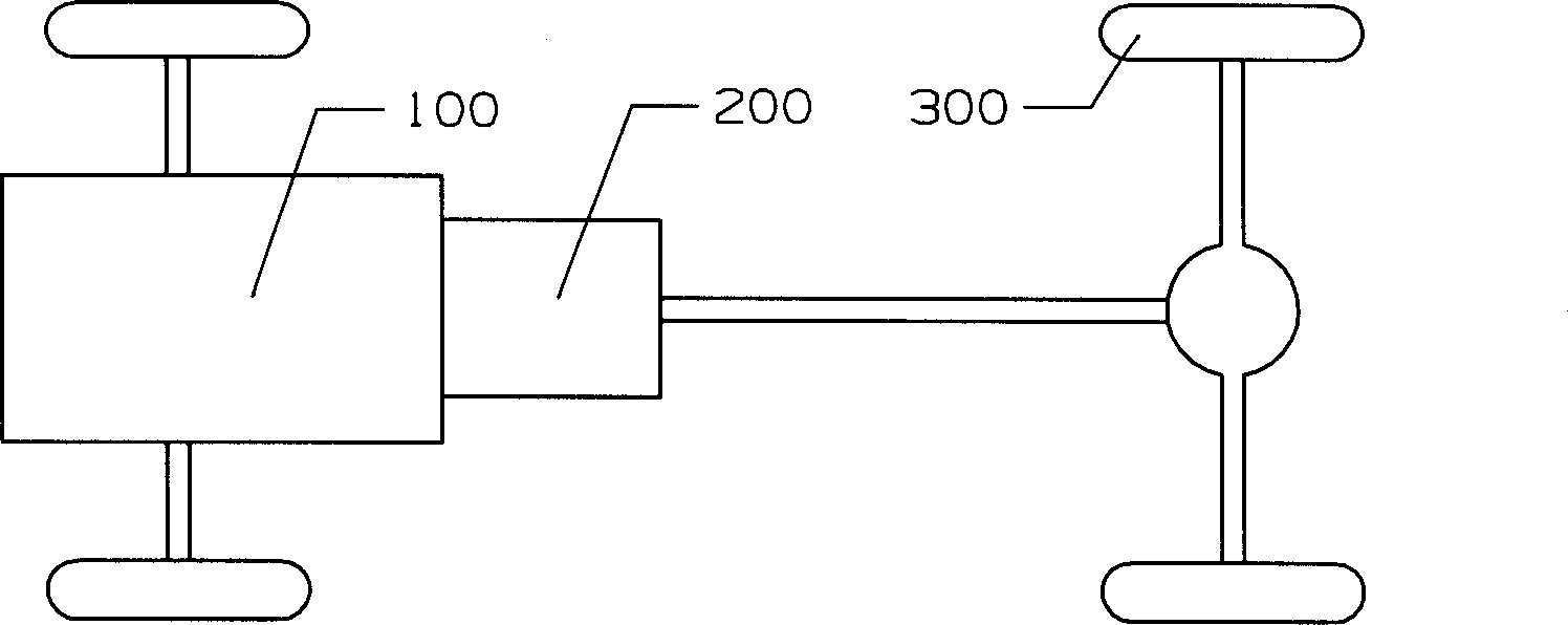
[0068] See Figure 1A , The figure schematically shows the structure of the automobile drive system, including a power source 100, a transmission 200 and a load 300 (ie wheels, etc.). The power source 100 is an engine, an electric motor or other prime movers. For ease of description, the present invention uses an engine As a power source. The transmission device 200 is installed between the power source 100 and the load 300, and the power output by the power source 100 is transferred to the wheels 300 to rotate after being torque-changed and shifted by the transmission device 200, thereby driving the vehicle forward or backward. The present invention improves the transmission device 200 therein.

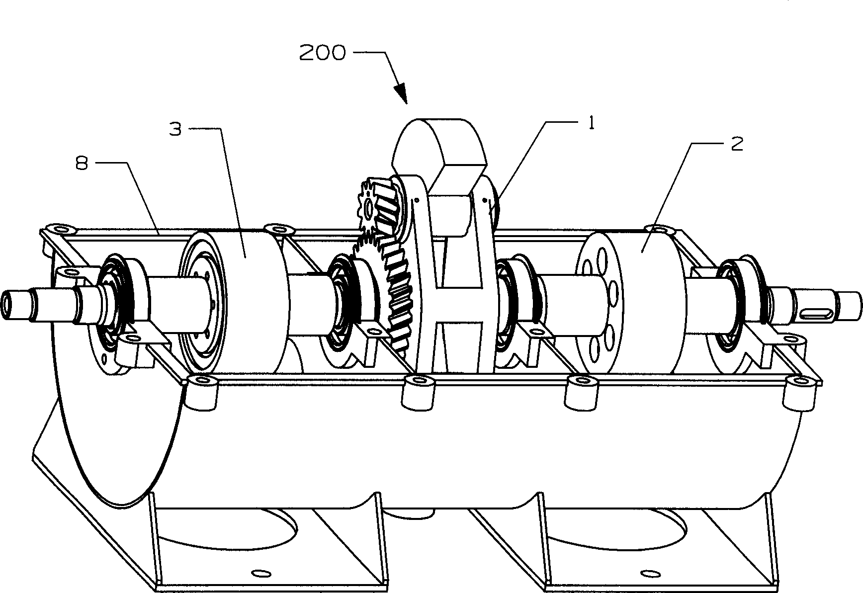
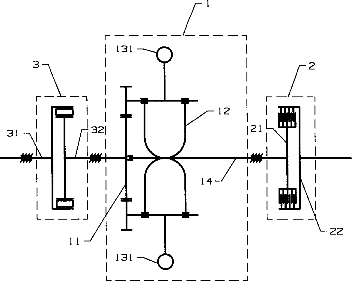
[0069] See Figure 1B According to the present invention, the mechanical continuously variable automatic transmission device 200 includes a housing 8 and a torque converter 1, a first one-way clutch 2 and a second one-way clutch 3 installed in the housing 8, Such as figure 2 As shown in...


PUM


Abstract

The invention discloses a driving device of mechanic zooming automatic velocity variation, which consists of case and torque variation system in the case, wherein the torque variation system contains input part, rotatable rack, at least one eccentric structure component on the rack and output part; the input part and rack can rotate individually, whose rotary shafts coincide mutually; each eccentric structure component contains an eccentric quality block, which is activated by output part to rotate around itself axis; the one-way clutch is set in front of the torque variation system; the one-way clutch is partly connected on the rack output part directly. The driving device adjusts the output rotary speed and torque automatically according to the load, which accomplishes the function of zooming automatic velocity variation.

Description

Technical field: [0001] The invention relates to a continuously variable transmission device, in particular to a continuously variable automatic transmission device applied to a vehicle. Background technique [0002] The application of the continuously variable automatic transmission device in the vehicle makes the driving of the vehicle change from manual gear to automatic gear. Automatic transmission cars are more and more popular among car buyers because of their convenient operation, smooth speed increase, and high driving safety. In the prior art, there are mainly two types of continuously variable automatic transmissions for realizing automatic transmission: hydraulic automatic transmissions and metal belt continuously variable automatic transmissions. These two types of continuously variable transmissions generally have many shortcomings, which are detailed as follows: [0003] The hydraulic automatic transmission includes two types: a hydraulic coupling and a hydraulic to...

Claims


Application Information

Patent Timeline
IPC IPC(8): F16H61/14B60K17/08F16H57/02
CPCF16H33/185
Inventor 韩文明
Owner 韩文明
Learn More