Vertical heat tube cooling machine

A cooler and heat pipe technology, applied in vertical heat pipe coolers, F28C 3/12 category, can solve the problems of difficult recycling of waste heat, high air leakage rate and energy consumption, and high mechanism failure rate, so as to achieve less environmental pollution and reduce Effect of air leakage and reduction of process energy consumption

Inactive Publication Date: 2006-05-24
刘继清
View PDF2 Cites 3 Cited by
  • Summary
  • Abstract
  • Description
  • Claims
  • Application Information

AI Technical Summary

Problems solved by technology

[0003] Looking at the sintering machines (equipment) used by various metallurgical iron and steel enterprises at home and abroad, there are various structural forms such as annular coolers or flat and tower vibrating coolers, mainly blowing or pumping belt coolers and annular coolers. Type coolers, they all have the disadvantages of large air consumption, low exhaust temperature, high air leakage rate and energy consumption
According to the investigation, there is the "Atmospheric Pressure Futeng Furnace High-temperature Ash Cooler" with the patent No. 88109985, which has a complex structure; there is also the "Vertical Sinter Cooler" with the patent application No. 93117175.x, which has its unique features , but the failure rate of the mechanism working in the high temperature environment such as the material gate and the material bell is too high to be implemented
In addition, there are patent No. 03227225.1 "Sintered ore plus atomized water cooling device" and patent No. 02139809.7 "Sintered ore plus water cooling method and its device". Waste heat is difficult to recycle

Method used


Image

  • Vertical heat tube cooling machine
  • Vertical heat tube cooling machine
  • Vertical heat tube cooling machine

Examples


Embodiment Construction

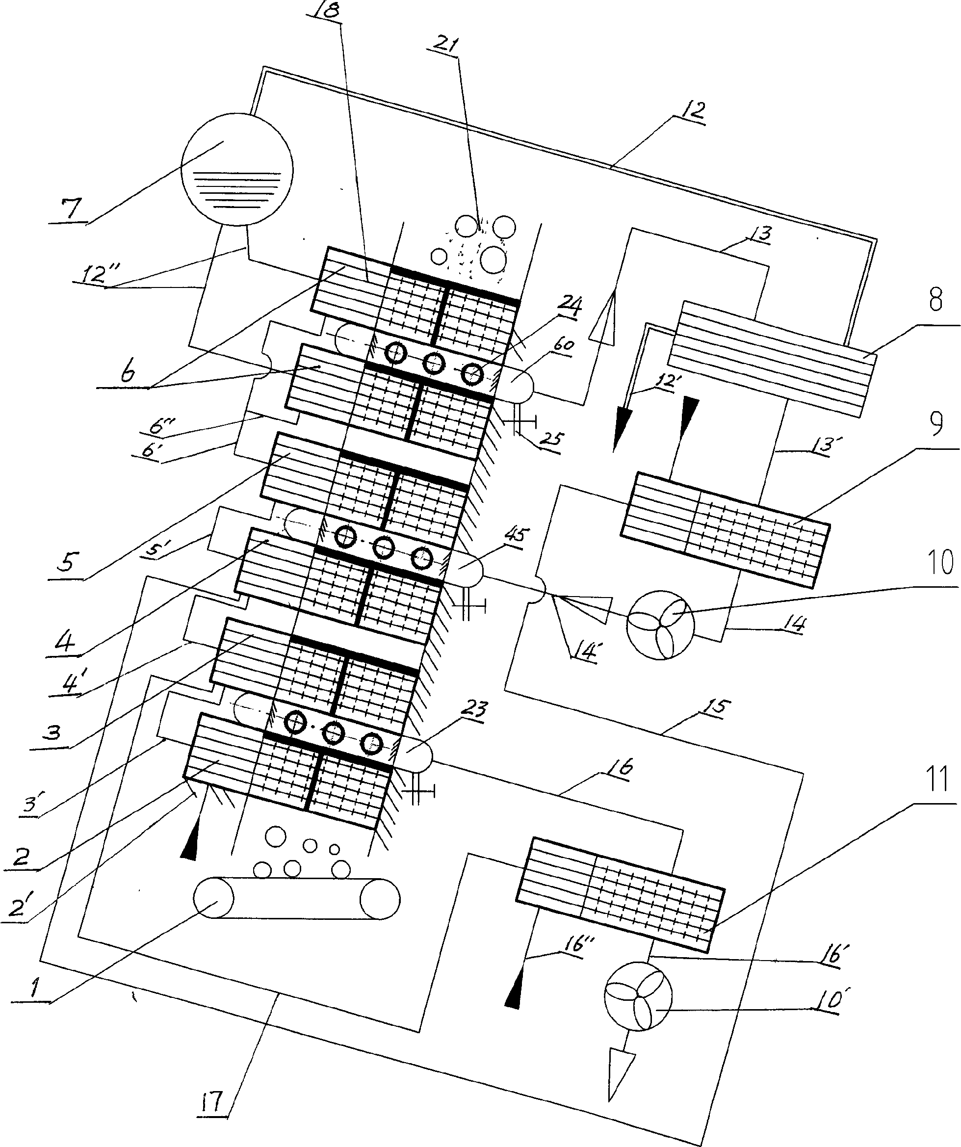
[0018] The specific implementation manners of the present invention will be further described in detail below in conjunction with the accompanying drawings.

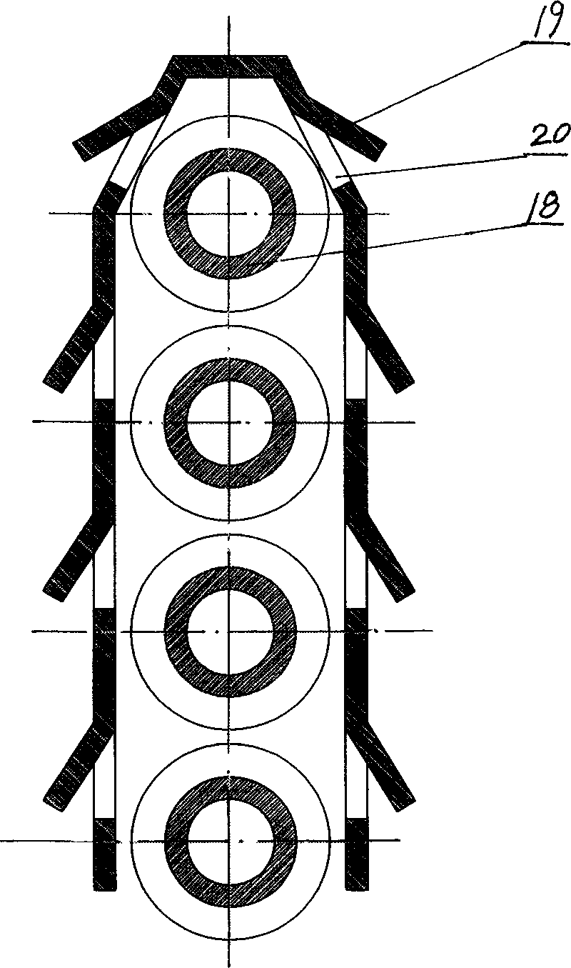
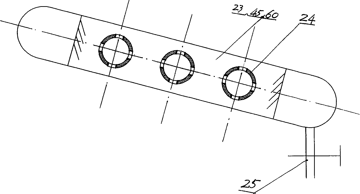
[0019] As shown in the drawings, the vertical heat pipe cooler is composed of a cold ore discharge chain plate machine 1, a fixed support 2', a low-temperature heat pipe preheater 2, a heat pipe preheater 3, and a medium-temperature heat pipe preheater 4 , high-temperature heat pipe preheater 5, heat pipe evaporator 6, annular air duct 23 or 45 or 60, steam drum 7, steam superheater 8, flue gas heat pipe preheater 9 or 11, fan 10 or 10', soft water pipe 3 ' or 4' or 5' or 6' or 16" or 15 or 17, steam pipe 12 or 12", steam delivery pipe 12', air pipe 13 or 13' or 14 or 14' or 16 or 16', The low-temperature heat pipe preheater 2, medium-temperature heat pipe preheater 4, high-temperature heat pipe preheater 5, and heat pipe evaporator 6, which are composed of heat pipes 18, are arranged sequentially from the bottom up. He...


PUM


Abstract

Upright type heat pipe chilling unit is in use for recycling residual heat. Being entered into heat pipe evaporator and heat pipe preheater in high, middle and low temperature, high heat granules are discharged from chain plate machine. Passing through the preheater and cooling end of heat pipe in the heat pipe evaporator, deoxidized pressed soft water absorbs heat so that temperature is increased gradually to form two-phase flow of vapor-liquid. After entering into steam drum and steam superheater, the said two-phase flow becomes saturated steam gas, which is output to users. Cold air is inducted to annular flue by fan; and another flow of gas from preheater is inducted to annular flue by negative pressure. Through heat exchange at preheater, the confluent flow in the annular flue is drained to dust removal system. The confluent flows of hot air from feeding port and hot air from evaporator enters into steam superheater and bustle pipe etc. and return back to the preheater circularly.

Description

technical field [0001] The invention relates to a cooling machine capable of recovering waste heat of high-temperature particles, in particular to a vertical heat pipe cooling machine applicable to recovering waste heat of sintering ore, which belongs to the category of F28C 3 / 12. Background technique [0002] In iron and steel enterprises, the energy consumption of the sintering process ranks second only to ironmaking in the iron and steel production process, and each ton of sintering ore consumes more than 50kg of standard coal. Based on the current annual production of 1.5 billion tons of sintered ore by metallurgical enterprises, the annual consumption of 75 million tons of standard coal is required. However, in the existing sinter production process, only a few sinter coolers are equipped with waste heat recovery devices, which recover the waste heat in the flue gas of a small part of the coolers. Due to the small amount of steam produced, and its low temperature or pr...

Claims


Application Information

Patent Timeline
Patent Type & Authority Applications(China)
IPC IPC(8): F27D17/00C22B1/26
CPCY02P10/25
Inventor 刘继清
Owner 刘继清
Why Eureka
Try Eureka