Iron-based parts and method for manufacture thereof
A manufacturing method and component technology, applied in the field of surface modification technology, can solve problems such as nickel plating peeling, and achieve improved hardness and strength, excellent sliding running-in and corrosion resistance, excellent sliding running-in and wear resistance. The effect of resistance and corrosion resistance
- Summary
- Abstract
- Description
- Claims
- Application Information
AI Technical Summary
Problems solved by technology
Method used
Image


Examples
Embodiment 1、2
[0062] Mix atomized iron powder (Atmel 300M: manufactured by Kobe Steel Works), electrolytic copper powder (CE15: manufactured by Fukuda Metal Foil Powder Industry), graphite powder (manufactured by Suusu Eastan) and lubricant (zinc stearate ), compress the mixed powder in a metal mold, and sinter in butane-modified gas at a temperature of 1120°C. In addition, the composition of the sintered body was copper: 1.5% by mass, the amount of bonded carbon: 0.2% by mass, and the density was 6.7Mg / m 3 .
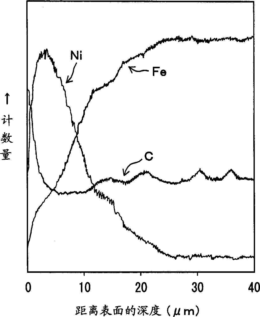
[0063] A sample (Example 1) and a sample (Example 2) in which electroless nickel plating was performed on the sintered body were prepared. Here, the plating thickness was set at 5 μm. In addition, the phosphorus content in the electroless nickel plating layer is set to a low concentration. Under such conditions, each sample was sequentially subjected to quenching and tempering treatments. Quenching was carried out by oil quenching after heating at a temperature of 850° C. for 2 h...
Embodiment 3、4
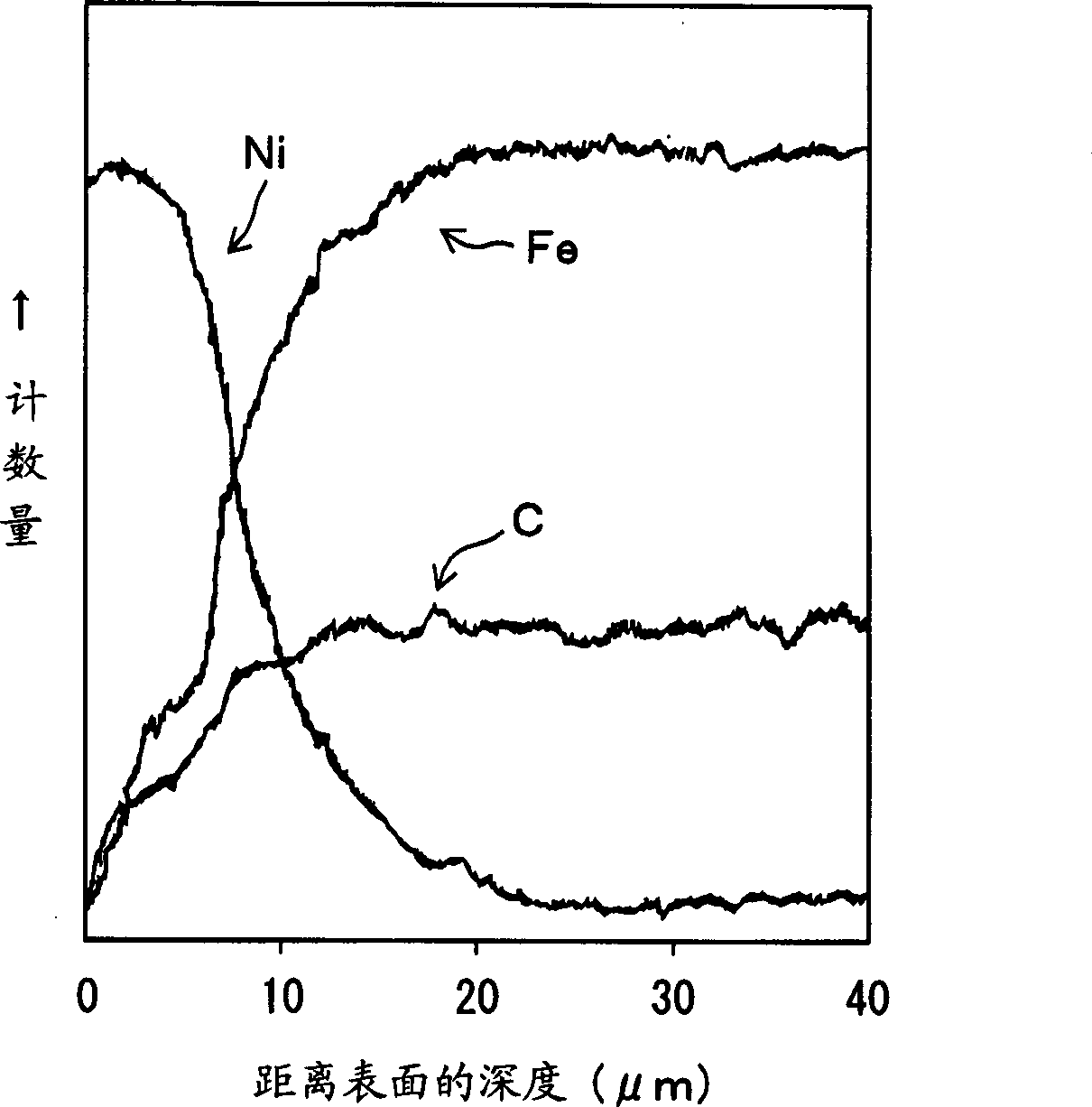
[0065] The base material was produced using the same raw material powder and manufacturing method as in the above-mentioned Examples 1 and 2, except that the bonded carbon content of the sintered body was 0.6% by mass. A sample (Example 3) and a sample (Example 4) in which electroless nickel plating was performed on the sintered body were prepared. Oil quenching and tempering treatments were carried out after heating at a temperature of 880° C. for 1 hour in a gas atmosphere with a carbon potential of 0.1%, respectively.
Embodiment 5
[0067]The base material was produced by the same manufacturing method as in Examples 3 and 4 above, and the bonded carbon content of the sintered body was 0.6% by mass. The sintered body was electroplated with nickel in the same manner as in the above examples, and then heated at a temperature of 850° C. for 2 hours in a gas atmosphere with a carbon potential of 0.6%, quenched and tempered, and a sample was produced.
[0068] Table 1 shows the cross-sectional hardness for Examples 1-5 produced as described above.
[0069] Table 1
[0070] Distance from surface(mm)
0.1
0.3
0.5
1.0
Example 1
770
765
730
675
Example 2
765
725
700
655
Example 3
580
600
630
660
Example 4
600
620
640
665
Example 5
740
725
700
670
[0071] According to Table 1, Example 1 and Example 2, the surface layer port...
PUM
| Property | Measurement | Unit |
|---|---|---|
| Thickness | aaaaa | aaaaa |
Abstract
Description
Claims
Application Information
 - Generate Ideas
- Intellectual Property
- Life Sciences
- Materials
- Tech Scout
- Unparalleled Data Quality
- Higher Quality Content
- 60% Fewer Hallucinations
Browse by: Latest US Patents, China's latest patents, Technical Efficacy Thesaurus, Application Domain, Technology Topic, Popular Technical Reports.
© 2025 PatSnap. All rights reserved.Legal|Privacy policy|Modern Slavery Act Transparency Statement|Sitemap|About US| Contact US: help@patsnap.com