Automatic cascade type refrigerating and circulating system with unfixedly proportioned hybrid medium

A technology of mixed working fluid and circulating system, applied in refrigerators, refrigeration and liquefaction, compressors with cascade operation, etc., can solve the problems of limited application scope, high energy consumption, and reduced evaporation temperature of high-temperature components, etc. Achieve the effect of avoiding insufficient liquid supply, ensuring normal work, and shortening cooling time

Inactive Publication Date: 2006-07-26
DALIAN FISHERIES UNIVERSITY
View PDF0 Cites 1 Cited by
  • Summary
  • Abstract
  • Description
  • Claims
  • Application Information

AI Technical Summary

Problems solved by technology

[0003] However, since the current separation technology cannot guarantee that the two refrigerants can be completely separated, the refrigerant with low purity will produce a temperature glide when evaporating at a fixed pressure, that is, the evaporation temperature of the high-temperature component will decrease, and the evaporation temperature of the low-temperature component will decrease. rise, and its temperature difference is larger
For this reason, the existing throttling element applied to single (pure) refrigerant - the automatic expansion valve with a static superheat of 2-8°C cannot be used in the automatic cascade refrigeration cycle system, otherwise it will cause liquid supply Insufficient or compressor liquid return and other phenomena, so that the existing automatic cascade refrigeration cycle system has the following disadvantages:
[0004] The mixed working fluid must have a fixed ratio. For example, if R13 / R12 is used as the mixed working fluid, the ratio must be 0.247:0.753 (Reference 1). When the refrigerant in the refrigeration cycle system leaks (such as system repair, valve replacement parts, etc.), its ratio will change, which will directly lead to changes in system parameters, and the refrigerator will not work normally or efficiently
At this time, all the remaining refrigerant in the system must be released, and then the mixed refrigerant prepared in proportion by the manufacturer must be added again, which will not only cause a lot of waste of refrigerant, but also cause pollution to the environment
[0005] In view of the above problems in the existing automatic cascade refrigeration cycle system, its application range is limited, especially it is difficult to apply in large and medium-sized refrigeration devices such as tuna quick-freezing and refrigeration, so that the existing tuna quick-freezing and refrigeration can only use volume Two-stage compression refrigeration system with large size, high energy consumption, low efficiency and poor economy

Method used


Image

  • Automatic cascade type refrigerating and circulating system with unfixedly proportioned hybrid medium

Examples


Embodiment 1

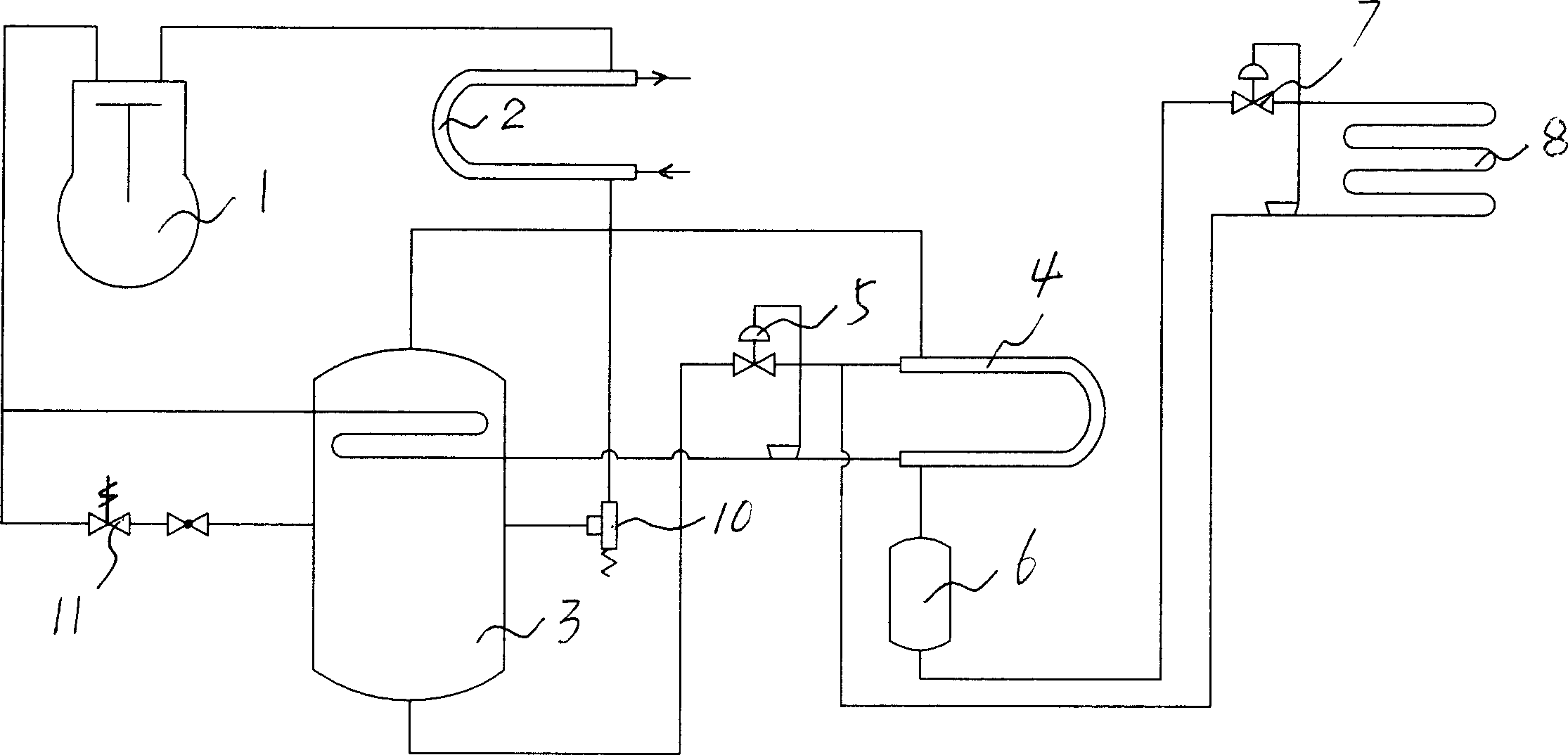
[0017] There is a compressor 1, and a decondenser 2 is connected to the exhaust port of the compressor 1, and the outlet of the decondenser 2 is connected to the vapor-liquid separator and liquid storage 3, and the vapor-liquid separator and liquid storage 3 The gas outlet of the evaporative condenser is directly connected to the evaporative condenser 4, the liquid outlet is connected to the evaporative condenser 4 through the throttling element 5, the gas outlet of the evaporative condenser 4 is connected to the suction port of the compressor 1, and the liquid outlet is passed through The liquid receiver 6 and the throttling element 7 are connected to the evaporator 9, and the outlet of the evaporator 9 is connected to the steam suction port of the compressor 1. The refrigerants used are R12 and R23, and R134a and R23 can also be used without a fixed ratio. , the charging amount can meet the normal working needs of the evaporative condenser and the evaporator respectively, and...

Embodiment 2

[0022] The refrigerant uses R22 and R23.

[0023] Others are the same as in Embodiment 1, except that a condensing pressure regulating valve 10 is connected between the partial condenser 2 and the vapor-liquid separator and liquid reservoir 3, and a back pressure valve or the like can be used.

[0024] When R22 and R23 are used as the mixed working fluid, after the components are condensed and separated, due to the influence of mutual solubility, when the suction pressure of the compressor reaches atmospheric pressure, the evaporation temperature of the high-temperature components in the evaporative condenser reaches -50°C below, while the low-temperature components are only about -70°C. Due to the low evaporation temperature of the high-temperature component (R22) in the evaporative condenser, the condensation pressure of the low-temperature component is very low, which will reduce the exhaust pressure of the compressor, causing the high-temperature part (R22) in the deconden...

Embodiment 3

[0027] Other as embodiment 1 or embodiment 2, just be connected with relief valve 11 between gas-liquid separator and accumulator 3 and compressor 1, relief valve 11 can be electromagnetic valve, and electromagnetic valve is connected with compressor pressure sensor, relay control. When the compressor starts to start, the exhaust pressure will be between 2.0 and 3.0Mpa, and the opening pressure of the pressure relief valve is set to 1.8Mpa. After the unit is started, the pressure sensor and relay will open the solenoid valve to release the pressure, so that the compressor will discharge. The steam pressure is maintained at 1.8Mpa for a period of time. Since the work of the decondenser is not affected by pressure relief, the high-temperature component refrigerant is normally throttled and evaporated, gradually reducing the temperature and pressure of the evaporative condenser, and soon (about 10 minutes) the exhaust pressure of the compressor is reduced to below 1.8Mpa , the p...


PUM


Abstract

The invention relates to an automatic layered refrigeration cycle system with mixed working substance and without fixed proportion. It comprises a throttle element (5) connecting the evaporation condenser (4), and a throttle element (7) connecting the evaporator (9). It is characterized in that: said throttle element (5) is an automatic expansion valve whose stable over-cold degree is 0 to -20Deg. C; and the throttle element (7) is an automatic expansion valve whose stable over-heat degree is 9-20Deg. C. The invention can overcome the defects of present technique which need fixed proportion. And it uses aforementioned automatic expansion valves as throttle elements; therefore, it can adjust the liquid supply automatically according to the outlet over-heat (over-cold) degree of evaporator and evaporation condenser when the mixed working substance is in unfixed proportion, to avoid the lack of liquid supple or the reflux of compressor to confirm the normal operation of said refrigeration cycle system. The invention can be used in large refrigeration systems.

Description

Technical field: [0001] The invention relates to an automatic cascade refrigeration cycle system, in particular to an automatic cascade refrigeration cycle system which does not require a fixed ratio of mixed working fluids. Background technique: [0002] The known automatic cascade refrigeration cycle system is provided with a compressor, and a decondenser is connected with the exhaust port of the compressor. The vapor outlet of the separator is directly connected to the evaporative condenser, the liquid outlet is connected to the evaporative condenser through a throttling element, the vapor outlet of the evaporative condenser is connected to the suction port of the compressor, and the liquid outlet passes through the liquid receiver 1. The throttling element is connected with the evaporator, and the outlet of the evaporator is connected with the suction port of the compressor. The automatic cascade refrigeration cycle system needs to be filled with two kinds of refrigeran...

Claims


Application Information

Patent Timeline
Patent Type & Authority Applications(China)
IPC IPC(8): F25B7/00
Inventor 程有凯
Owner DALIAN FISHERIES UNIVERSITY
Why Eureka
Try Eureka