Unlock instant, AI-driven research and patent intelligence for your innovation.

Optical receptacle

A technology of optical socket and optical fiber, which is applied in the field of optical socket, can solve the problems of sensitivity deterioration at the receiving side, 20R noise of the light receiving element, etc., and achieve the effects of high reproducibility, high connection loss, and improved reliability

Active Publication Date: 2006-07-26
KYOCERA CORP
View PDF5 Cites 3 Cited by
  • Summary
  • Abstract
  • Description
  • Claims
  • Application Information

AI Technical Summary

Problems solved by technology

[0021] Thus, as shown in FIG. 18, when the optical receptacle 74T for transmission and the optical receptacle 74R for reception are simultaneously fixed by the metal case 25, the electric signal for driving the light-emitting element 20T passes through the optical receptacle 74T made of metal, and leaks to the metal receptacle. The housing 25 generates noise to the light receiving element 20R, so there is a problem that the sensitivity on the receiving side deteriorates
[0022] In addition, since the metal sleeve of the optical receptacle 74T on the transmitting side becomes an antenna to emit electromagnetic waves, the outer periphery of the optical communication transmitter and receiver needs to be shielded by forming a metal shield to prevent electromagnetic wave leakage. On the contrary, the metal sleeve of the optical receptacle 74R on the receiving side The sleeve picks up external noise, and there is also a problem that the sensitivity on the receiving side deteriorates, so it is necessary to improve the noise characteristics

Method used


Image

  • Optical receptacle
  • Optical receptacle
  • Optical receptacle

Examples


no. 1 Embodiment approach

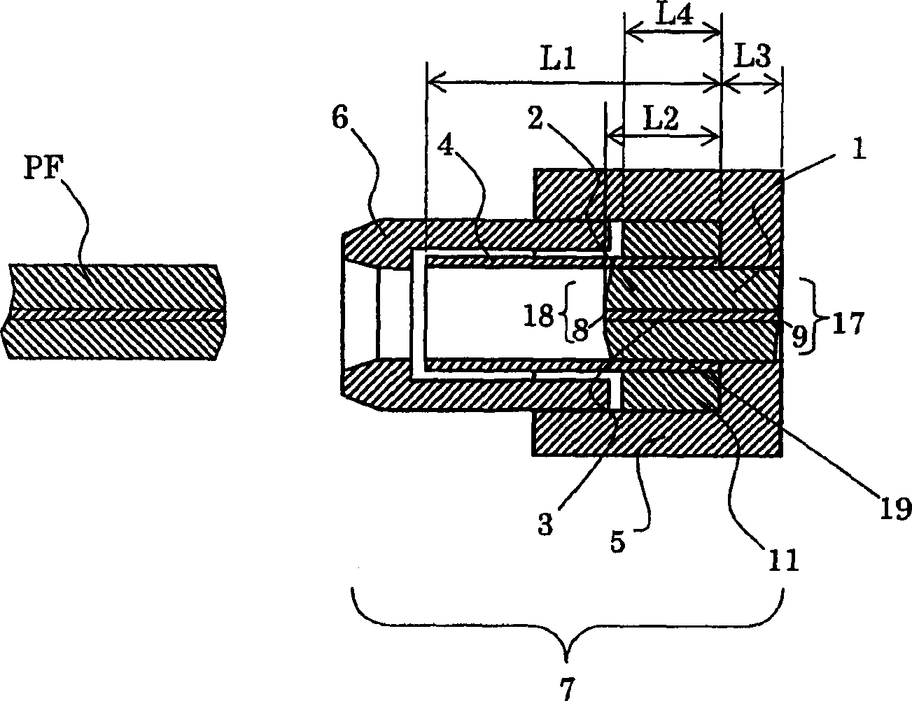
[0059] Figure 1A It is a cross-sectional view showing the first embodiment of the present invention, and consists of the following components: a fiber post 1 for inserting and fixing an optical fiber in a ferrule 2; a holder 5 and a sleeve housing for fixing the rear end 17 of the fiber post 1 6; and the sleeve 4 used to keep the plug ferrule PF connected to the front end 18 of the fiber post 1, and the sleeve 4 is inserted and held on the front end 18 of the fiber post 1.

[0060] Here, the retaining ring 11 is formed by filling the overlapping outer peripheral side surfaces 19 of the fiber posts 1 of the sleeve 4 with resin. Thereby, the said sleeve 4 does not incline, and since it is an elastic body, it has the effect of reducing inclination.

[0061] Next, let the length of the sleeve 4 be L1, the overlapping length of the sleeve 4 and the fiber post 1 be L2, the overlapping length of the holder 5 and the fiber post 1 be L3, and the fiber post 1 and the retaining ring Th...

no. 2 Embodiment approach

[0086] image 3 It is a cross-sectional view showing the second embodiment of the present invention, by inserting and fixing the optical fiber 3 in the fiber post 1 in the ferrule 2; fixing the holder 5 and the sleeve housing 6 at the rear end of the fiber post 1; The sleeve 4 is formed by holding the ferrule PF connected to the front end of the fiber post, and the front end 18 of the fiber post 1 is inserted into the sleeve 4 .

[0087] The sleeve 4 used at this time is as image 3 As shown, a thick portion 4a is formed. The outer diameter of the end portion inserted into and held by the fiber post 1 is processed into a trapezoidal shape, and its wall thickness is larger than that of the portion holding the plug ferrule PF. Thereby, the holding force of the thick part 4a can be improved.

[0088] In addition, the thickness of the thick portion 4 a is preferably 1.5 to 2.5 times the thickness of other portions. This is because if the thickness portion 4a is thinner than the...

no. 3 Embodiment approach

[0124] Figure 7 It is a cross-sectional view showing a third embodiment of the present invention. The precision sleeve 4 made of ceramic materials such as zirconia and alumina is fixed in the holder 5 of stainless steel with good weldability such as SUS304 by pressing. In addition, the metal flange 12 is press-fitted or adhesively fixed in the holder 5 without contact. Furthermore, a metallic ferrule stopper 13 is press-fitted and fixed to the inner diameter of the sleeve 4 .

[0125] Like this, through electric insulation flange 12 and clamper 5, when being used as the optical receptacle 7 of both sending and receiving of the optical module used in the optical transceiver, even if it is fixed by the metal case at the same time, it will not The following problems will occur: that is, the electrical signal driving the optical module for transmission also passes through the metal optical socket, leaks to the metal casing, and generates noise to the optical module for receptio...


PUM


Abstract

An optical receptacle where a rear end portion of a fiber stub having an optical fiber in a through-hole of a ferrule is fixed to a holder and a sleeve for holding a plug ferrule is held at the fore-end portion of the fiber stub, wherein a holder ring is provided on an outer peripheral surface where the fiber stub and the sleeve are superposed. The structure realizes an optical receptacle shorter in length, improves connection loss relative to the inclination of the plug ferrule, and provides excellent reproducibility of connection loss.

Description

technical field [0001] The present invention relates to an optical socket used in optical communication modules and the like. Background technique [0002] An optical module for converting an optical signal into an electrical signal is configured by accommodating an optical element such as a semiconductor laser or a photodiode in a housing, and introducing or exporting an optical signal through an optical fiber (JP-A-11-240741, JP-A-2001-66468 ). [0003] Among the above-mentioned optical modules, the receptacle-type optical module composed of connecting connectors is equipped with an optical element 20 at the rear of the optical receptacle 70 shown in FIG. . [0004] As shown in FIG. 14, the above-mentioned optical socket 70 is constituted by: a metal ring 82 made of ceramic materials such as zirconia and aluminum oxide, and an optical fiber 83 made of quartz glass or the like is inserted and fixed in the through hole of the metal ring 82. The rear end of the fiber post ...

Claims


Application Information

Patent Timeline
Patent Type & Authority Applications(China)
IPC IPC(8): G02B6/38G02B6/42
Inventor 伊藤宏树田中强松本俊之
Owner KYOCERA CORP