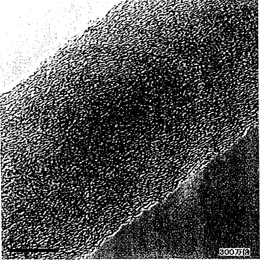
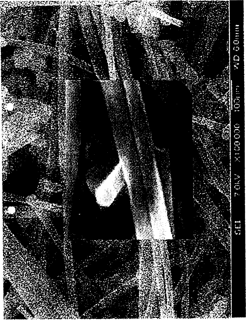
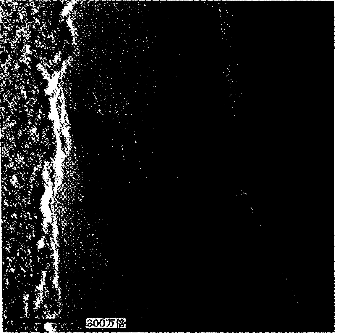
Microscopic carbon fiber with a variety of structures
A carbon fiber and fine technology, applied in the field of fine carbon fibers, can solve the problems of easy deformation of fibers, difficult to disperse, and difficult to decompose agglomerated particles, so as to reduce defects, improve dispersion, and improve bending rigidity.
- Summary
- Abstract
- Description
- Claims
- Application Information
AI Technical Summary
Problems solved by technology
Method used
Image
Examples
Embodiment 1
[0110] Using the CVD method, using toluene as a raw material to synthesize fine carbon fibers.
[0111] synthesis device such as Figure 8 shown.
[0112] As a catalyst, a mixture of ferrocene and thiophene was used, and the synthesis was carried out in a hydrogen reducing atmosphere. Toluene, the catalyst, and hydrogen were heated to 375° C., supplied to a production furnace, and allowed to react at a temperature of 1200° C. for 8 seconds. Atmospheric gas is separated by a separator and recycled. The hydrocarbon concentration in the feed gas was 9% by volume.
[0113] The tar content of the fine carbon fibers of the synthesized intermediate material (first intermediate material) was 10%.
[0114] Next, the fiber was heated up to 1200°C and held for 30 minutes to perform hydrocarbon separation treatment, and further, high-temperature heat treatment was performed at 2500°C. Hydrocarbon separation and high temperature heat treatment process equipment such as Figure 9 show...
Embodiment 2
[0119] The synthesis apparatus shown in Fig. 10 was used.
[0120] Using benzene as the carbon raw material, after dissolving the catalyst ferrocene and thiophene, it is gasified at 380°C and then introduced into the production furnace. The temperature of the forming furnace was 1150° C., and the atmosphere gas in the furnace was a hydrogen atmosphere. The residence time of hydrogen gas and raw material gas in the furnace was 7 seconds. The tar content of the carbon fibers (first intermediate) recovered downstream of the furnace was 14%.
[0121] Next, after heat-treating the fiber (first intermediate) at 1200° C. for 35 minutes, the specific surface area of the carbon fiber (second intermediate) was measured and found to be 33 m 2 / g. I determined by Raman spectroscopy D / I G is 1.0.
[0122] Furthermore, with respect to the magnetic flux density, the magnetoresistance value of the fine carbon fiber after high-temperature heat treatment at 2500°C is negative, and has ...
Embodiment 3
[0124] The fine carbon fibers obtained in Example 1 were measured using an X-ray diffraction apparatus. For comparison, graphite was also measured using an X-ray diffraction device. The X-ray diffraction spectrum obtained according to the measurement results is as follows Image 6 As shown, since the peak intensity of the fine carbon fibers obtained in Example 1 was weak, the comparison was magnified 10 times.
[0125] From this result, both have peaks at around 77° that are equivalent to the reflection of the graphite (110) plane. The graphite sample had a peak at around 83° corresponding to the reflection of the graphite (112) plane, but this was not found in the fine carbon fibers of Example 1. Therefore, the fine carbon fibers of the present invention do not have the three-dimensional regular structure of graphite.
[0126] Also, from this result, the interplanar spacing of the obtained fine carbon fibers was 3.388 angstroms.
PUM
| Property | Measurement | Unit |
|---|---|---|
| Specific surface area | aaaaa | aaaaa |
| Interplanar spacing | aaaaa | aaaaa |
Abstract
Description
Claims
Application Information
 - R&D
- Intellectual Property
- Life Sciences
- Materials
- Tech Scout
- Unparalleled Data Quality
- Higher Quality Content
- 60% Fewer Hallucinations
Browse by: Latest US Patents, China's latest patents, Technical Efficacy Thesaurus, Application Domain, Technology Topic, Popular Technical Reports.
© 2025 PatSnap. All rights reserved.Legal|Privacy policy|Modern Slavery Act Transparency Statement|Sitemap|About US| Contact US: help@patsnap.com


