Quality factor controllable shearforce detection controller

A technology of detection control and quality factor, applied in the field of scanning near-field optical microscopy, which can solve the problems of low quality factor, unreachable, high detection sensitivity, etc.

Inactive Publication Date: 2006-09-20
INST OF CHEM CHINESE ACAD OF SCI
View PDF0 Cites 3 Cited by
  • Summary
  • Abstract
  • Description
  • Claims
  • Application Information

AI Technical Summary

Problems solved by technology

Due to the low quality factor (Q-value) of this piezoelectric bimorph, high detection sensitivity cannot be achieved

Method used


Image

  • Quality factor controllable shearforce detection controller

Examples


Embodiment Construction

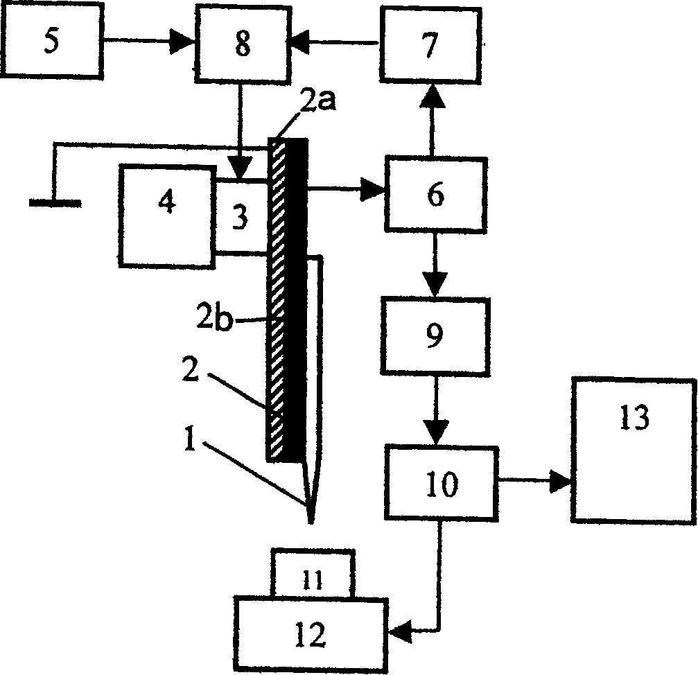
[0026] see figure 1 . The asymmetric piezoelectric bimorph 2 with a thickness of 0.4 mm is cut and ground to make a rectangular sheet with a length of 14 mm and a width of 1.5 mm. One end (one side of the metal sheet) of the piezoelectric bimorph 2 is glued on the piezoelectric ceramic block 3 on the scanning probe microscope body 4, and a section of the metal sheet 2a with a length of 2 mm is reserved for grounding, and the other end forms a Cantilever beam 2b. Probe 1 is an optical fiber probe, which can be made of single-mode or multi-mode optical fiber by chemical etching or heating and stretching, and bonded to the cantilever beam 2b of the asymmetric piezoelectric bimorph 2, that is, the piezoelectric bimorph On the piezoelectric sheet of the wafer 2 (on the surface of the ceramic sheet), one end of the optical fiber stretches out about 1 mm of the asymmetric piezoelectric bimorph as the probe 1, and the other end of the optical fiber is coupled with a photodetector su...


PUM

PropertyMeasurementUnit
thicknessaaaaaaaaaa

Abstract

This invention relates to controlled quality factor applied shear detecting control device. One end of asymmetric piezo double wafer is fixed on piezo ceramics to form cantilever beam structure, probe is pasted to surface of the wafer along length direction of the wafer. The ceramics is used to drive the wafer on its resonance frequency and drive probe vibrate, the wafer generates piezo voltage by piezoelectric effect the piezo signal is sent t Q-value control circuit after amplified, and it is used to drive the wafer block along with original driven signal to realize control of Q-value between 100-1000. The wafer resonance amplitude and phase changed when the optical fiber probe is effect by shearing force between the probe and sample, so the piezo voltage changed, and the changing is used as feedback signal to sent to feedback control circuit of scanning probe microscope to realize space control between the probe and the sample.

Description

technical field [0001] The invention relates to a scanning probe microscopy technique, in particular to the fields of scanning near-field optical microscopy and the like. Specifically, it relates to a shear force detection and control device with controllable quality factor (Q-value). Background technique [0002] Scanning near-field optical microscopy is a new microscopic imaging technology developed by combining scanning probe microscopy with optical technology. This technology replaces the optical lens with an optical probe, and adopts the imaging method of point-by-point scanning of the probe in the near field of the sample surface, which can simultaneously provide the sample surface topography and optics (including: absorption, scattering, polarization and fluorescence, etc.) at the nanometer scale. ) information, which breaks through the limitation of light wave diffraction effect and makes the optical image resolution reach nanometer level. [0003] In scanning near...

Claims


Application Information

Patent Timeline
Patent Type & Authority Applications(China)
IPC IPC(8): G01N13/14G01N13/00G12B21/06G01Q20/04
CPCB82Y35/00G01Q10/045
Inventor 商广义杨德亮季恒星万立骏白春礼
Owner INST OF CHEM CHINESE ACAD OF SCI
Why Eureka
Try Eureka