Switching power converter

A power converter and switching technology, which is applied in the direction of conversion equipment with intermediate conversion to AC, can solve the problems of easily damaged switch 11, lack of adjustment and consumption of switching power converters, etc.

A power converter and switching technology, which is applied in the direction of conversion equipment with intermediate conversion to AC, can solve the problems of easily damaged switch 11, lack of adjustment and consumption of switching power converters, etc.

CN1848644AInactive Publication Date: 2006-10-18SYST GEN

Image

  • Switching power converter
  • Switching power converter
  • Switching power converter

Examples


Embodiment Construction

[0056] In order to enable the examiner to have a better understanding and understanding of the structural features and achieved effects of the present invention, I would like to provide a diagram of a better embodiment and a detailed description, as follows:

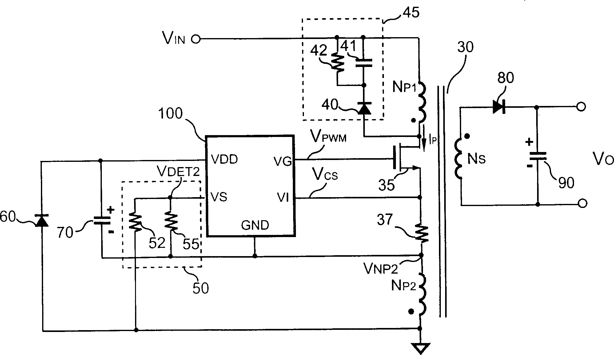
[0057] see figure 2 , is a circuit diagram of a switching power converter of a preferred embodiment of the present invention. As shown in the figure, the switching mode power converter of the present invention includes a transformer 30 for storing energy and transferring the stored energy from a primary side of the transformer 30 to a secondary side of the transformer 30 . Wherein, the primary side of the transformer 30 is provided with a first primary side winding N P1 with a second primary winding N P2 , and the secondary side of the transformer 30 is provided with a secondary side winding N S . The first primary side winding N P1 with the second primary winding N P2 Coupled to the power supply rail of the switc...


PUM


Abstract

A power converter of switching over type consists of a transformer with the first primary winding and the second primary winding being separately connected to positive and negative electric rails, a switch connected between two said windings, a control circuit coupled to switch and the second primary winding, a supply capacity for providing power to control circuit, a dipolar body coupled to negative rail and supply capacity, a leakage inductance for storing energy when switch is on and for releasing energy to supply capacity through dipolar body when switch is off.

Description

Technical field: [0001] The present invention relates to a power converter, in particular to a switching power converter. Background technique: [0002] By the way, power converters have been widely used to provide adjustable voltage and current. At present, the focus of research on power converters is how to make power converters more efficient and save power. Switching mode power converters usually include a control unit, a switch and a transformer, wherein the control unit is used to sense the output voltage and / or output current of the switching mode power converter, and generate a control signal to control switching and adjustment of the switch The output voltage and / or output current of the switching mode power converter. [0003] see figure 1 , which is a circuit diagram of a conventional switching power converter. As shown in the figure, the conventional switching power converter includes a transformer 10, which includes a primary side winding N P , primary and s...

Claims


Application Information

Patent Timeline
18 Oct 2006
Publication
CN1848644A
IPC
H02M3/28
Inventors
æšć€§ć‹‡