Micromechanical thermalelectric-stack infrared detector compatible with co-complementive metal oxide semiconductor technology and preparing method

An infrared detector and thermopile technology, applied in the field of infrared detectors, can solve the problems of inability to obtain a large infrared absorption area, poor CMOS process compatibility, unfavorable device performance arraying, etc., to achieve good device performance and good compatibility , low cost effect

Inactive Publication Date: 2006-10-25
SHANGHAI INST OF MICROSYSTEM & INFORMATION TECH CHINESE ACAD OF SCI
View PDF0 Cites 18 Cited by
  • Summary
  • Abstract
  • Description
  • Claims
  • Application Information

AI Technical Summary

Problems solved by technology

At present, the micromachined infrared thermopile generally adopts the back etching method, such as the method adopted in the article "Infrared thermopile sensors with high sensitivity and very low temperature coefficient" by J Schieferdecker et al. The CMOS process has poor compatibility, which increases the difficulty of the process and the manufacturing cost is also high
Recently, some micromachined infrared thermopile have al

Method used


Image

  • Micromechanical thermalelectric-stack infrared detector compatible with co-complementive metal oxide semiconductor technology and preparing method
  • Micromechanical thermalelectric-stack infrared detector compatible with co-complementive metal oxide semiconductor technology and preparing method
  • Micromechanical thermalelectric-stack infrared detector compatible with co-complementive metal oxide semiconductor technology and preparing method

Examples


Embodiment 1

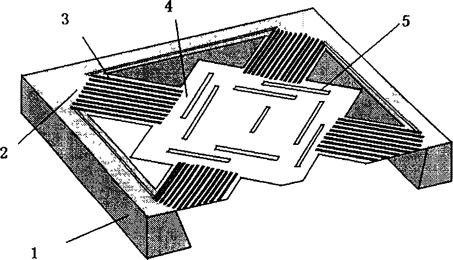
[0026] The structure of this embodiment can be found in figure 1 . Its production process is as follows:

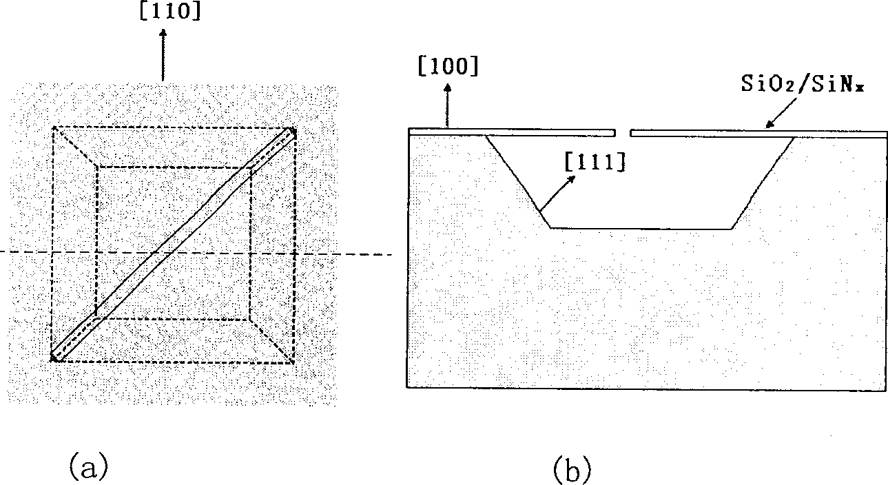
[0027] 1. Deposit a layer of SiO on (100) single crystal silicon by LPCVD 2 / Si 3 N 4 Double-layer dielectric film structure, the total film thickness is about 5000 Ȧ. Then grow a layer of polysilicon with a thickness of about 4000 Ȧ on it, and then grow about 1000 Ȧ of silicon oxide, such as Figure 5 - Shown in (a).

[0028] 2. After photolithography, BOE (Buffered Oxide Etch, buffered oxide etchant) and other processes are used to form silicon oxide window patterns on the surface, photoresist is used as an ion implantation mask layer, and P and B plasma are implanted into polysilicon to form polysilicon resistance strips. As a thermopile couple material such as Figure 5 -shown in (b).

[0029] 3. After photolithography harden the film, BOE wet-etches the silicon oxide on the surface of the remaining polysilicon, ion dry-etches the polysilicon outside the resis...

Embodiment 2

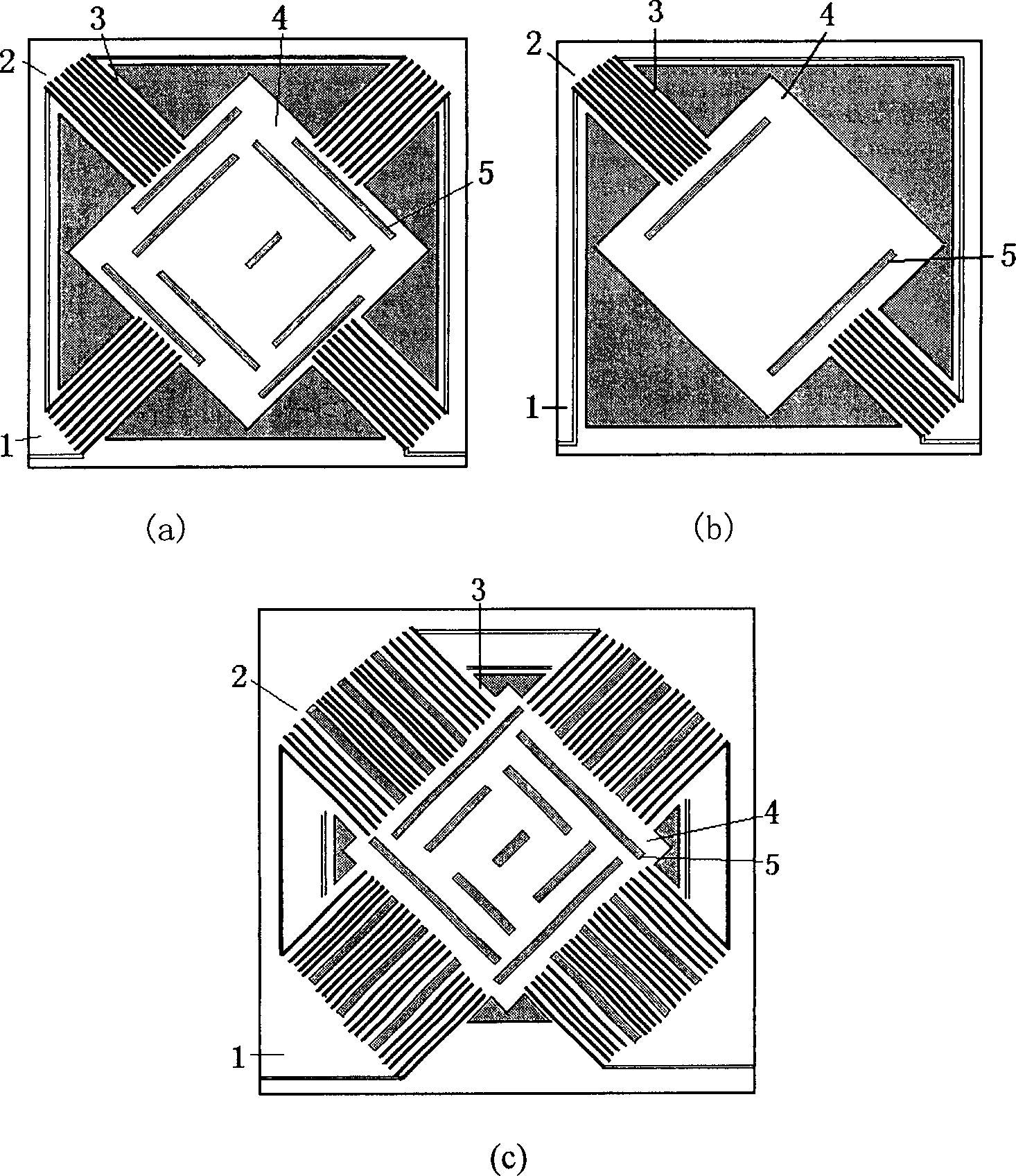
[0035] The top view of the structure of this embodiment can be found in figure 2 -(b), all the other are with embodiment 1.

Embodiment 3

[0037] The top view of the structure of this embodiment can be found in figure 2 -(c), all the other are with embodiment 1.


PUM


Abstract

This invention relates to a micro-mechanical thermopile infrared detector structure compatible with a complementary metal-oxide semiconductor, (CMOS) and its execution method characterizing in utilizing the erosion property of the anisotropy of a monocrystal silicon and applying a front specific open-end to realize a large area micro-mechanical thermopile structure by the front erosion, the character of the infrared detector is that a frame and a middle suspended infrared absorption region constitute a cold junction region and a hot junction region of the thermopile, a bracket arm is connected with the frame, the infrared absorption region and carries the thermopile and a long open-end covers the entire infrared absorption region.

Description

technical field [0001] The invention relates to a micromechanical thermopile infrared detector structure compatible with complementary metal oxide semiconductors (CMOS) and a manufacturing method thereof, and is especially suitable for manufacturing large array infrared detectors. The invention belongs to the field of infrared detectors. Background technique [0002] In recent years, the application of infrared detectors in public safety, medical diagnosis, environmental monitoring, security systems, astronomical research, assisted driving and real-time thermal detection of chips has attracted increasing attention. With the increasing popularity of applications, the requirements for miniature, sensitive, compact, secret and high reliability of infrared detection systems are also increasingly strong. Compared with traditional photon detectors, the uncooled infrared technology adopts the increasingly mature MEMS technology and uses photo-thermal-electric conversion to detect ...

Claims


Application Information

Patent Timeline
IPC IPC(8): H01L35/00B81B7/00B81C1/00G01J5/12H01L31/09H01L31/18H01L37/00
CPCY02P70/50
Inventor 李铁刘义冬王翊熊斌王跃林
Owner SHANGHAI INST OF MICROSYSTEM & INFORMATION TECH CHINESE ACAD OF SCI
Why Eureka
Try Eureka