
Method for collecting and treating reaction gases from a production plant for molten metal and dust-removing machine therefor

A technology of reactive gas and dust removal equipment, applied in lighting and heating equipment, chemical instruments and methods, separation methods, etc., can solve the problems of filter device damage, deflagration, restriction, etc., and achieve the effect of preventing overheating

Inactive Publication Date: 2006-11-01
PRIMETALS TECH AUSTRIA GMBH
View PDF4 Cites 4 Cited by
  • Summary
  • Abstract
  • Description
  • Claims
  • Application Information

AI Technical Summary

Problems solved by technology

These conditions lead to a significantly increased energy discharge from metallurgical vessels during charging of scrap metal into molten steel or vice versa
Overheated reaction gases are not cooled sufficiently during the short delivery time to the dust separation unit and cause overheating damage at the filter unit
Cooling gas mixing, mainly air, is limited because, briefly, a large amount of reaction gas requires a correspondingly large amount of cooling gas, which in turn leads to an uneconomical oversizing of filter equipment
[0008] In addition, the short-lived large amount of gas will cause incomplete combustion of decomposition products formed by the incidental materials of scrap metal due to lack of oxygen, and cause the incomplete combustion of reaction gases to be sucked into the piping system of the secondary dust removal equipment
If atmospheric air subsequently enters this duct system, in particular if cooling gas is injected before entering the dust separation device, deflagration can occur, leading to destruction of, inter alia, the filter device

Method used


Image

  • Method for collecting and treating reaction gases from a production plant for molten metal and dust-removing machine therefor
  • Method for collecting and treating reaction gases from a production plant for molten metal and dust-removing machine therefor
  • Method for collecting and treating reaction gases from a production plant for molten metal and dust-removing machine therefor

Examples


Embodiment Construction

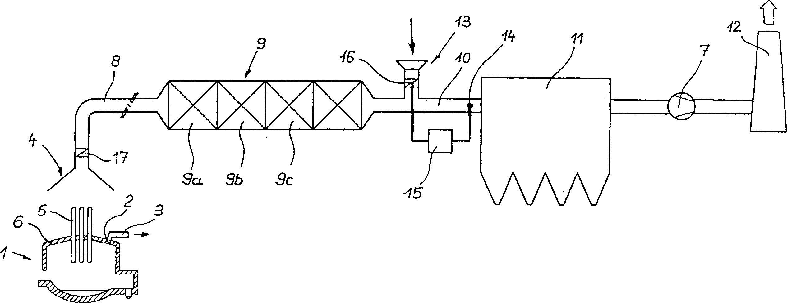
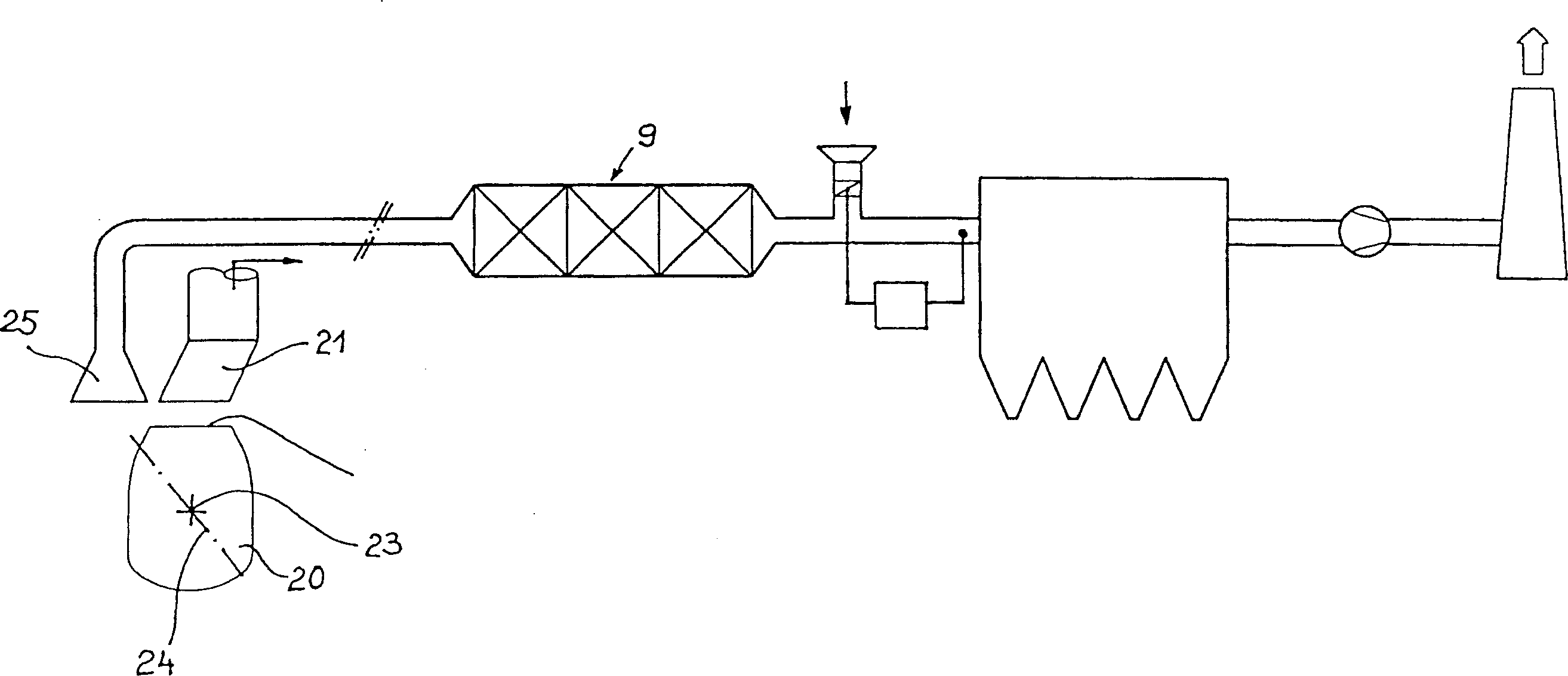
[0044] figure 1 with 2 The secondary dedusting equipment according to the present invention is schematically shown based on two typical uses in the steelmaking basic material industry.

[0045] figure 1 An electric arc furnace 1 commonly used for melting steel scrap is shown. The electric arc furnace has a roof opening 2 which is adjoined in a sealed manner by a flow channel 3 forming part of a primary dedusting device, which is not shown in detail and corresponds to known prior art. During the continuous smelting process and the subsequent molten steel treatment process, reaction gases are sucked out of the furnace through the flow channel 3 . An exhaust hood 4 for collecting reaction gases from the electric furnace is arranged above the electric arc furnace, below the roof of the furnace chamber (not shown), especially during the operation of charging scrap into the existing molten steel due to the The reaction gas formed by the combustion of impurities in non-metals. D...


PUM


Abstract

The invention relates to a method for collecting and treating reaction gases from a production plant for molten metal. Substances used, containing metal, are introduced into a metallurgic container in a solid of liquid form and are converted under the effect of fuel and reaction substances and the hot, gaseous and dust-charged reaction gases discharged from the metallurgic container are partially guided into a primary dust-removing process and partially into a secondary dust-removing process in associated dust separating devices. In order to reliably remove dust in a short space of time from large and hot amounts of reaction gas with the smallest dimensioned dust-removing machine possible, the reaction gas which is guided to the secondary dust-removing process passes through a heat accumulator prior to the dust-removing process and the reaction gas which has a temperature which is higher than the wall temperature of the accumulator elements, releases heat to the heat accumulator. Said accumulated heat is re-discharged to subsequent reaction gases (or suctioned ambient air) having a temperature which is lower than the wall temperature of the accumulator elements.

Description

technical field [0001] The present invention relates to a method for collecting and processing reaction gases from a molten metal production plant, wherein a metal-containing charge in solid or liquid form is introduced into a metallurgical vessel and reacted under the action of fuel and reactive materials, and the The gaseous and dust-laden hot reaction gas is sent partly to the primary dedusting process and partly to the secondary dedusting process in the associated dust separation plant and to the relevant dedusting plant. [0002] In the primary dedusting process, the reaction gases formed during the continuous metal production process are cooled and dedusted, while in the secondary dedusting process the reaction gases generated during the charging of scrap metal and pig iron are preferably further treated. [0003] In particular, the present invention relates to a method for processing reaction gases from a steelmaking plant, in which iron-containing charges such as pig i...

Claims


Application Information

Patent Timeline
IPC IPC(8): C21C5/38B01D39/00B01D46/00C21C5/40F27B1/22F27B3/26F27D17/00F27D19/00F28D17/00
CPCC21C5/40F27B1/22F27B3/26F27D17/003F27D17/004F27D17/008F27D19/00F27D2019/0021Y02P10/25
Inventor 阿尔弗雷德·阿尚佩尔安东·恩格尔曼
Owner PRIMETALS TECH AUSTRIA GMBH
Features
  • Generate Ideas
  • Intellectual Property
  • Life Sciences
  • Materials
  • Tech Scout
  • Unparalleled Data Quality
  • Higher Quality Content
  • 60% Fewer Hallucinations
Learn More