
Large-scale grounding network detection technology and detection system for power plant and transformer substation

A detection technology and detection system technology, which is applied in the field of large-scale grounding grid detection technology and its detection system in power plants and substations, can solve problems such as inability to make correct judgments, corrosion, and high potential of the grounding grid, and achieve fast measurement speed, The effect of accurate and comprehensive data

Active Publication Date: 2006-11-22
河北天雷电力设备科技有限公司
View PDF0 Cites 32 Cited by
  • Summary
  • Abstract
  • Description
  • Claims
  • Application Information

AI Technical Summary

Problems solved by technology

The current problems are: 1. Some areas have not paid enough attention to the inspection and transformation of the grounding grid. In recent years, there have been accidents that have caused power plants and substations to stop due to poor grounding grids.
2. Relevant technical issues such as the relationship between corrosion and soil quality, the selection of thermal stability time and the determination of cross-sectional area, etc. are summarized or listed, so as to revise the grounding regulations and construction specifications as soon as possible to guide the design, construction, transformation and maintenance of the grounding grid. run
It is difficult to find the grounding grid and welding connection of each phase of the project
If all the grounding grids are dug up for inspection, all the high and low voltage equipment in the factory and station will lose grounding protection, which will affect the normal working grounding.
This will cause greater danger to the normal operation of the power system, electrical equipment and personal safety in power plants and substations
[0009] There are many defects in the existing measurement method: 1. The ground grid, the ground bus bar, and the ground lead wire of the high-voltage equipment are severely corroded, even if the cross-sectional area is only 1 square millimeter, or even rusted, due to the existence of iron oxide, the existing The measuring device can not test out
Whether it can meet the short-circuit capacity requirements under the current system operation mode, it is impossible to make a correct judgment
2. When the grounding busbar and the grounding down-conductor of high-voltage equipment are disconnected for some reason, and the fault current can no longer be conducted, it is difficult to test and check out the existing devices
3. When an asymmetrical short circuit occurs in the power system, if the grounding grid does not meet the thermal stability requirements, a high potential difference will be generated on the grounding grid
Its interference to the relay protection device in the station, the threat to the insulation of the secondary cable, and the harm to the DC system and the power system of the station cannot be predicted.
Therefore, it is impossible to formulate practical preventive measures
4. When an asymmetrical short circuit occurs in the power system or a grounding fault occurs in the high-voltage equipment in the station, since the effective cross-sectional area of ​​the grounding network wire, the conduction capacity of the faulty short-circuit current on the grounding network and the grounding device are not known, the thermal stability of the grounding network will also vary. can't be tested
5. When an asymmetrical short-circuit fault occurs in the power system, the contact voltage generated on the electrical equipment in the station and the distribution of the step voltage generated on the site in the station cannot be accurately tested and calculated
6. The grounding grid of the later expansion and reconstruction project of the same factory and station is not connected with the grounding grid of the previous project
However, due to the shielding grounding of the protective secondary cable, one end is connected to the terminal box of the new equipment, while the other end is connected to the grounding busbar of the protection device in the previous main control room, making it impossible to measure the serious defects in the grounding network

Method used


Image

  • Large-scale grounding network detection technology and detection system for power plant and transformer substation
  • Large-scale grounding network detection technology and detection system for power plant and transformer substation
  • Large-scale grounding network detection technology and detection system for power plant and transformer substation

Examples


Embodiment 1

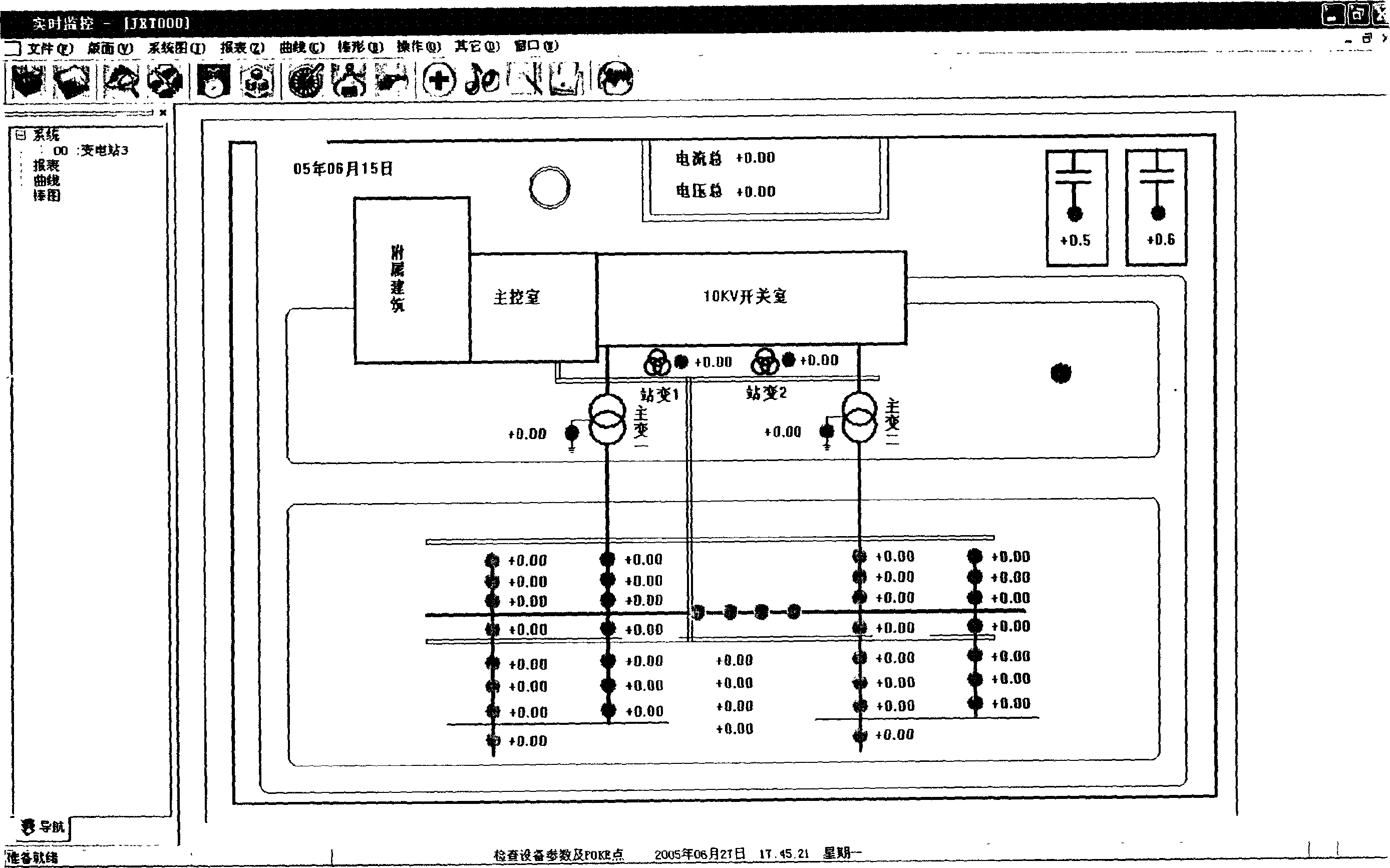
[0031] Example 1: In a certain substation, the ground potential map measured without applying current and voltage to the ground grid in the actual measurement is as follows image 3 shown. From the ground potential diagram, it can be intuitively judged that the two high-voltage equipment in the upper right corner should have a problem with the grounding, and they belong to the equipment with grounding obstacles.

Embodiment 2

[0032] Example 2: In a certain substation, in the actual measurement of the grounding grid, the detection is first carried out according to the technical steps of this detection, and it is judged that several of the equipment have problems, and after verification, it is obtained as follows: Figure 4 The ground potential map, and a comparative test, measured: the isolation transformer no-load voltage 75v pre-adjusted current output in the large, medium and small three gears respectively measured a diameter of 18 mm, a cross-sectional area of ​​254 square mm, and a 50-meter-long round steel The current value and voltage value passed on. Large gear, current 231A, voltage 47.6V, the calculated resistance value is 0.206 ohms. In the middle range, the current is 180A and the voltage is 37.6V. The calculated resistance value is 0.205 ohms. Small gear, current 81.5A, voltage 17V, the calculated resistance value is 0.208 ohms. First, through the ground potential diagram, it can be ju...


PUM


Abstract

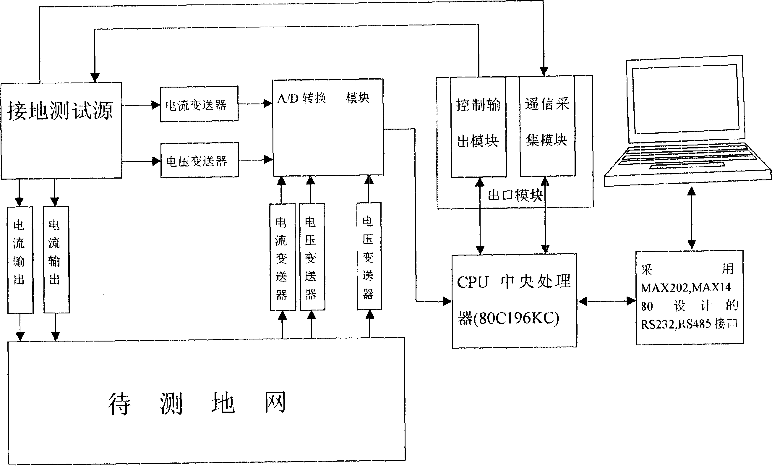
The related testing scheme for large-scale ground network of power plant and transformer substation comprises: (1) preparing; (2) without external voltage or current, measuring the normal network; (3) with voltage and current, measuring and obtaining data; (4) using computer to obtain the ground potential distribution graph, analyzing data to obtain the network report; (5) taking validation. This invention is fast and accurate.

Description

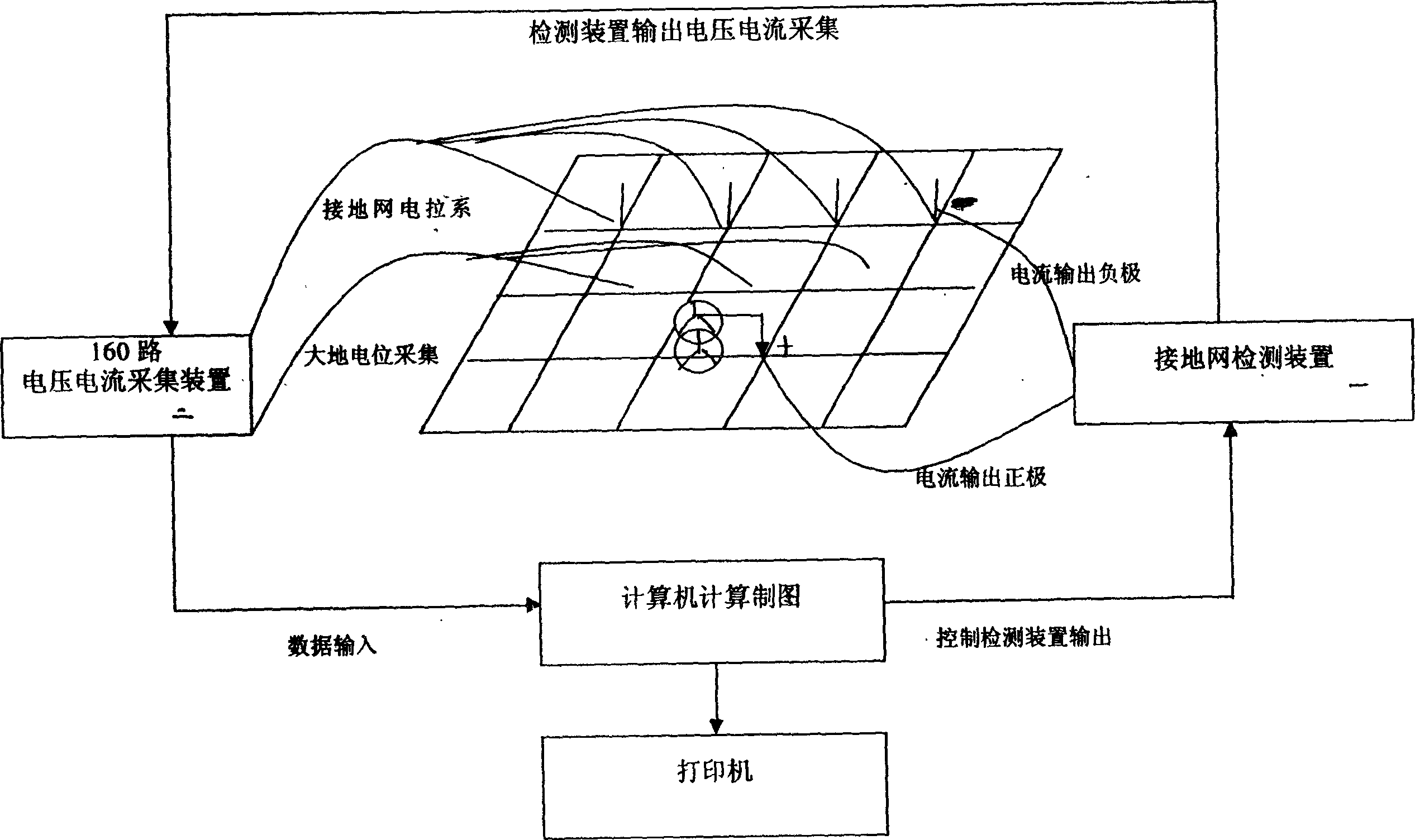
technical field [0001] The invention relates to a technology and a detection system for detecting problems existing in large-scale grounding grids of power plants and substations. Background technique [0002] The grounding network of power plants and substations is a system network that integrates the four functions of working grounding, protective grounding, lightning protection grounding, and anti-static protection grounding of high-voltage and low-voltage electrical equipment and relay protection automatic devices in the power system. It is one of the important electrical equipment to ensure the safe operation of the power system. The grounding grid plays a vital role in the safe operation of the power system. [0003] At present, due to the problems of the grounding network, grounding lead wire and electrical equipment grounding of domestic power plants and substations, high voltage and high current flow into the low-voltage system, burning down the plant's electrical ...

Claims


Application Information

Patent Timeline
Patent Type & Authority Applications(China)
IPC IPC(8): G01R31/00G01R19/00G01R27/16
Inventor 高政高淑萍高永禄
Owner 河北天雷电力设备科技有限公司
Learn More