Partial fibre-optical passive tester and its application

A polarization-maintaining optical fiber and tester technology, which is applied to the field of testers for beat length parameters, and the field of polarization-maintaining optical fiber beat length testers, can solve problems such as inability to achieve, and achieve the effects of being easy to replace, not easy to break, and simple to adjust the optical path.

Inactive Publication Date: 2007-02-14
NANKAI UNIV
View PDF1 Cites 8 Cited by
  • Summary
  • Abstract
  • Description
  • Claims
  • Application Information

AI Technical Summary

Problems solved by technology

[0009] In addition, in patents JP59-81523, JP59-126225, JP58-223032, EU0291962A2, EU0249923A2, and US6229599B1, methods such as observation

Method used


Image

  • Partial fibre-optical passive tester and its application
  • Partial fibre-optical passive tester and its application
  • Partial fibre-optical passive tester and its application

Examples


Example Embodiment

[0055] Example

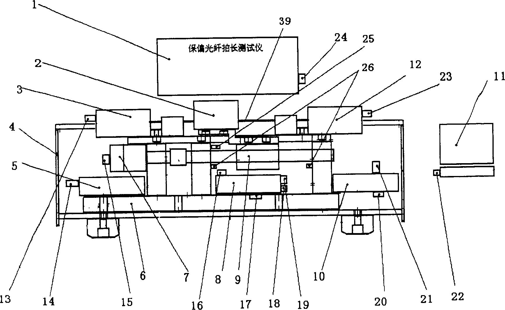
[0056] Such as figure 1 As shown, the present invention consists of liquid crystal touch screen 1, precision micro-displacement control devices 3, 6, 7, pressure applying device 2, optical path system, optical fiber transmission polarization state direct coupling adjustment device 3, 12, light source drive module 5, signal processing The analysis control system 8, the detector and the optical power detection module 10, and the upper computer analysis processing system 11.

[0057] The LCD touch screen is used in a human-computer interaction platform to input control parameters and display measurement data and measurement results. It is connected to the signal processing analysis control system 8 through interfaces 24 and 16. The pressure applying device 2 is connected to the screw nut 9 in the precision displacement control device. As the screw nut moves left and right, the optical fiber clamped between the bearing pair is subjected to a predetermined pressure, a...


PUM


Abstract

A beat tester of polarization preserving fiber is composed of accurate micro displacement control unit, signal pressing-analyzing control system, liquid touch screen display system, upper stream apparatus analysis- process system, direct -couple regulation unit of optical fiber transmission- polarization state, pressure exerting unit and light path system.

Description

technical field [0001] The invention relates to a polarization-maintaining optical fiber beat length tester, in particular to a tester for measuring the beat-length parameter of a polarization-maintaining optical fiber by using a pressure perturbation method, belonging to the fields of polarization-maintaining optical fiber testing and optical fiber sensing. Background technique [0002] The invention adopts the pressure perturbation method to measure the beat length parameter of the polarization maintaining optical fiber and to analyze its performance. The basic principle is that when linearly polarized light is incident at an angle of 45 degrees to the fast and slow axis of the polarization-maintaining fiber, due to the birefringence of the fiber, the transmitted light will form beats along the transmission direction and its optical power will change according to a certain period. The pressure perturbation is applied along the radial direction of the fiber, and it is displ...

Claims


Application Information

Patent Timeline
IPC IPC(8): G01M11/00G01N21/00
Inventor 张德生盛秋琴董孝义
Owner NANKAI UNIV
Why Eureka
Try Eureka