Liquid crystal lens element and optical head device

A liquid crystal lens and component technology, which is applied to optical recording heads, beam guiding devices, optics, etc., can solve the problems of complicated mechanism design, easy short circuit, and easy disconnection of the transparent electrode 320.

Inactive Publication Date: 2007-02-14
ASAHI GLASS CO LTD
View PDF5 Cites 22 Cited by
  • Summary
  • Abstract
  • Description
  • Claims
  • Application Information

AI Technical Summary

Problems solved by technology

[0010] However, when such a movable lens group 160 is used, a pair of lenses 161 and 162 and a driver 163 are required, so there is a problem that the size of the optical head device 100 is increased, and the mechanism design is complicated due to the movement.
[0030] However, in this liquid crystal diffrac

Method used


Image

  • Liquid crystal lens element and optical head device
  • Liquid crystal lens element and optical head device
  • Liquid crystal lens element and optical head device

Examples


example 1

[0310] Below, refer to Image 6 The details of the liquid crystal lens element 20 of the present invention shown in the second embodiment will be described.

[0311] Example.

[0312] First, a method of manufacturing the liquid crystal lens element 20 will be described.

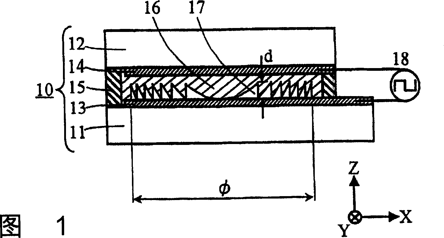
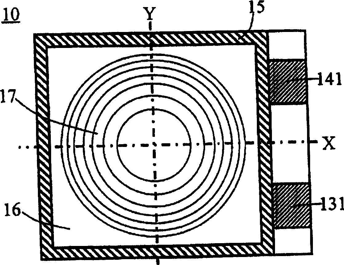
[0313] A transparent conductive film (ITO film) is formed on a glass substrate of the transparent substrate 11 as the transparent electrode 13 . Then coat the transparent electrode 13 with a refractive index n s (=1.66) uniform refractive index material, that is, photosensitive polyimide, was formed into a film thickness d (=5.5 μmm).

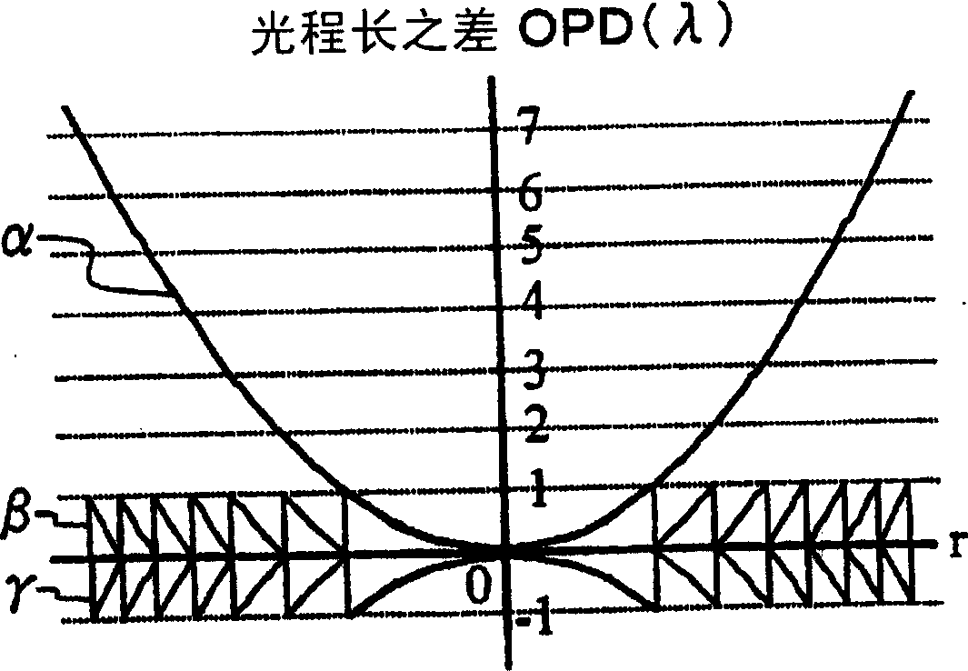
[0314] Then, using the equivalent of image 3 A step mask whose ultraviolet transmittance is distributed in the radial direction as in the shape of the curve β, irradiates the photosensitive polyimide with ultraviolet rays, sinters the step mask pattern, and then develops it. As a result, in the region of the effective diameter φ (= 4.9 mm), the cross-sectional shape is s...

example 2

[0344] Next, it will be described that the liquid crystal lens element 20 of the aforementioned [Example 1] is housed in the Figure 11 A specific example of the optical head device 70 according to the sixth embodiment shown. In addition, since the structure of this optical head apparatus 70 was already demonstrated in 6th Embodiment, it is abbreviate|omitted here.

[0345] When recording and reproducing a single-layer disc D for DVD with a cover layer thickness of 0.60mm, if the applied voltage of the liquid crystal lens element 20 is V 0 = about 2.5V, the incident light is focused on the information recording layer by the objective lens 6 .

[0346] For the double-layer disc D used for DVD, if the applied voltage of the liquid crystal lens element 20 is V +1 (=0V), the incident light is focused on the information recording layer with a cover layer thickness of 0.57mm, and if the facility applied voltage is about V-1 (=6V), the incident light is focused on the information r...

example 3

[0351] Next, the volume resistivity p F Greater than or equal to the volume resistivity ρ of the liquid crystal 16 LC For examples of materials, refer to Image 6 Described below.

[0352] First, a method of manufacturing the concave-convex portion 17 in the liquid crystal lens element 20 will be described.

[0353] On the transparent electrode 13 formed into a film on the glass substrate of the transparent substrate 11, the ordinary light refractive index n of the liquid crystal 16 is formed by sputtering. o Substantially equal refractive index n s (=1.507) uniform refractive index material SiOxNy (here, x and y represent the element ratio of O and N) thin film. Here, a Si sputtering target and a discharge gas in which oxygen and nitrogen are mixed in Ar gas are used, and the refractive index n is formed in this way. s A transparent SiOxNy film with a uniform refractive index and a film thickness d (= 2.94 μm). Relative permittivity ε of SiOxNy F is 4.0, volume resisti...


PUM

PropertyMeasurementUnit
Maximum radiusaaaaaaaaaa
Thicknessaaaaaaaaaa
Thicknessaaaaaaaaaa

Abstract

The present invention provides liquid crystal lens element comprising no movable part, having a small size, having a lens function capable of being subjected to stable spherical aberration correction including the power component corresponding to the focus variation of the incident light. The liquid crystal lens element has a variable focal length to the light transmitted through a liquid crystal(16) interposed between a pair of transparent substrates(11, 12). The variable focal length can be varied with the voltage applied to the liquid crystal(16). The liquid crystal lens comprises transparent electrodes(13, 14) provided to the respective transparent substrates(11, 12) and used to apply a voltage to the liquid crystal(16) and an irregular part(17) which has a serrated cross section and a rotational symmetry with respect to the optical axis and is formed of a transparent material on one side of the transparent electrode(13). The liquid crystal(16) is placed at least in the recesses of the irregular part(17) so as to vary the substantial index of refraction of the liquid crystal(16) depending on the applied voltage.

Description

technical field [0001] The present invention relates to a liquid crystal lens element and an optical head device, in particular to a liquid crystal lens that can be switched to a plurality of different focal lengths according to the magnitude of the applied voltage, and a device equipped with the liquid crystal lens for recording information on an optical recording medium and / or Replay optical head device. Background technique [0002] An optical recording medium (hereinafter referred to as an "optical disc") has an information recording layer formed on the light-incident side surface, and a cover layer formed of a transparent resin covering the information recording layer. As such an optical recording medium, the CD CDs and DVDs, etc. In addition, in the optical head device for recording and / or reproducing information on the DVD disc, a semiconductor laser with a wavelength of 660 nm is used as a light source, and an objective lens with an NA (numerical aperture) of 0.6 to...

Claims


Application Information

Patent Timeline
IPC IPC(8): G11B7/135G02F1/13G11B7/125G11B7/1353G11B7/1369G11B7/1376G11B7/1392
Inventor 大井好晴佐藤弘昌清水龙一郎野村琢治田边让大泽光生
Owner ASAHI GLASS CO LTD
Why Eureka
Try Eureka