Textile and non-woven cloth plasma surface treating device

A surface treatment device, plasma technology, applied in textiles and papermaking, fiber treatment, physical treatment, etc., can solve problems such as low efficiency, fiber material burns, uneven filamentary discharge, etc., and achieve current density and energy density. Reduced, improved uniformity, improved wettability

Active Publication Date: 2007-03-21
NANJING SUMAN PLASMA TECH CO LTD
View PDF0 Cites 21 Cited by
  • Summary
  • Abstract
  • Description
  • Claims
  • Application Information

AI Technical Summary

Problems solved by technology

But for large-scale industrial production, this discharge method has two important disadvantages: ① the discharge and reaction chamber are in a low pressure state, the vacuum system is essential, and the investment and operating costs of the industrial vacuum system are relatively high; ② In the process of industrial processing, it is necessary to continuously open the reaction chamber to take out the finished product, add the test sample, and then re-evacuate, fill in the working gas and discharge. This batch processing method is difficult to achieve continuous production, and the efficiency is not high.
DBD plasma has been used for plasma surface treatment, but DBD in air or other general gases at atmospheric pressure usually consists of filamentous streamer discharges, which have energy due to their uneven spatial distribution of current. Focusing on the streamer discharge, there will be two important problems when processing materials such as fabrics or non-woven fabrics: ①The local temperature of the streamer discharge is too high, which may easily cause local burns or perforations of the material during processing; The cloth is a heterogeneous material, and the plasma is unevenly distributed on the surface of these materials. The discharge is stronger in the mesh part of the material or the thinner part of the material, and the discharge is weaker in the part that needs plasma treatment.
However, due to the uniform distribution of the electric field in the discharge gap and the high breakdown field strength of the commonly used DBD with parallel plate electrode structure, uneven filamentary discharge will be formed once the breakdown occurs, so it cannot be used to treat materials such as textiles and non-woven fabrics.
Some auxiliary measures such as gas flow, reducing gas humidity, etc. can partially improve the uniformity of this discharge, but still cannot solve the problem of non-uniformity of filament discharge and damage to materials; and the wire-surface or wire-barrel electrode structure DBD is more likely to form uneven filamentary discharge, causing local burns or perforation of fibrous materials

Method used


Image

  • Textile and non-woven cloth plasma surface treating device
  • Textile and non-woven cloth plasma surface treating device
  • Textile and non-woven cloth plasma surface treating device

Examples


Embodiment 1

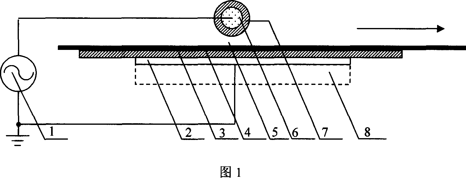
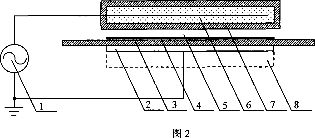
[0033] The structure of Embodiment 1 of the present invention is shown in FIG. 1 , and FIG. 2 is a schematic diagram of its side structure. The direction of the arrow in FIG. 1 is the transmission direction of the sample 4 . The high-voltage electrode in this embodiment is a high-voltage electrode dielectric tube 7 sealed and filled with metal powder 6 inside the tube. The high-voltage end of the high-frequency power supply 1 is inserted into the high-voltage electrode dielectric tube 7 through a wire. The grounding electrode is a metal plate 2 covered with a dielectric plate 3, the dielectric plate 3 is in close contact with the metal plate 2, and the ground terminal of the high-frequency power supply 1 is connected to the metal plate 2 through a wire. During specific installation, the metal powder 6 is poured into the high-voltage electrode dielectric tube 7 with one end sealed, and the high-voltage end wire of the high-frequency power supply 1 is inserted into the metal powd...

Embodiment 2

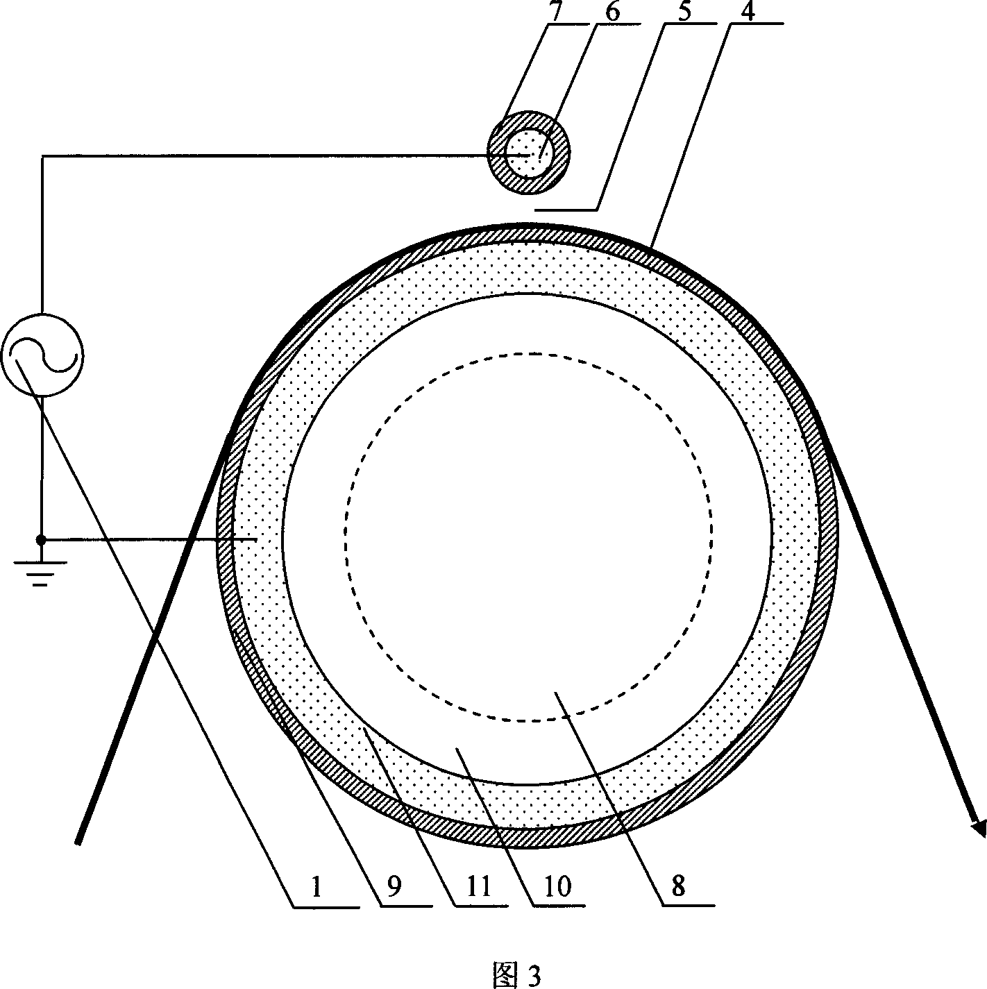
[0036] The structure of Embodiment 2 of the present invention is shown in Figure 3. The high-voltage electrode of this embodiment is a high-voltage electrode dielectric tube 7 sealed and filled with metal powder 6 in the tube. The high-voltage end of the high-frequency power supply 1 is inserted into the high-voltage electrode through a wire. Inside the medium pipe 7. The grounding electrode is a casing composed of an inner tube and an outer tube. The outer tube is a grounding electrode dielectric tube 9 whose curvature radius is greater than that of the high-voltage electrode dielectric tube 7. The curvature radius of the grounding electrode dielectric tube 9 is at least equal to that of the high-voltage electrode dielectric tube 7 times the radius of curvature. The inner tube is a metal tube 10, and the gap layer formed by the inner wall of the outer tube and the outer wall of the inner tube is sealed and filled with metal powder 6. The ground terminal of the high-frequency...

Embodiment 3

[0039] The structure of the third embodiment of the present invention is shown in Figure 4. In this embodiment, a plurality of high-voltage electrode dielectric tubes 7 sealed and filled with metal powder 6 are used. Four high-voltage electrode dielectric tubes 7 are arranged side by side as high-voltage electrodes. The high-voltage end of the high-frequency power supply 1 is inserted into the high-voltage electrode dielectric tube 7 through a wire. The grounding electrode is a metal plate 2 covered with a dielectric plate 3. The dielectric plate 3 is in close contact with the metal plate 2. The ground terminal of the high-frequency power supply 1 is connected to the metal plate 2 through wires. During specific installation, the metal powder 6 is poured into the high-voltage electrode dielectric tube 7 with one end sealed, and the high-voltage end wire of the high-frequency power supply 1 is inserted into the metal powder 6 until one end of the wire is close to the seal of the ...


PUM


Abstract

The present invention belongs to the field of gas discharge technology, and relates to a plasma surface treatment equipment for textiles and non-woven fabric. Said plasma surface treatment equipment for textiles and non-woven fabric includes high-frequency power supply, high-voltage electrode and grounding electrode. The high-voltage electrode is at least one medium tube whose interior is filled with metal powder and sealed or one metal tube whose exterior is covered with silicone rubber, the high-voltage end of said high-frequency power supply is inserted into the medium tube interior by means of conducting wire, and the grounding electrode is a metal electrode covered with medium plate or a metal rod whose exterior is covered with silicone rubber tube, the grounding end of said high-frequency power supply is connected with metal electrode by means of conducting wire. Said invention can be used for making large-area plasma surface treatment of textiles, non-woven fabric and paper material, etc.

Description

technical field [0001] The invention belongs to the technical field of gas discharge, in particular to a plasma surface treatment device for textiles and non-woven fabrics. Background technique [0002] The low-temperature plasma generated by gas discharge contains a large number of active particles of various types. These active particles can cause etching, oxidation, reduction, cross-linking, polymerization, grafting and other reactions on the surface of the material in contact with the material, causing the surface of the material to Changes in chemical composition and physical and chemical properties, such as changing the hydrophilicity, adhesion, dyeability, shrink resistance, antifouling and electrical conductivity of the surface of the material. This surface treatment method has the characteristics of simple process, easy operation, low energy consumption, and no pollution to the environment. In the textile industry, this method is used for etching activation, graft ...

Claims


Application Information

Patent Timeline
Patent Type & Authority Applications(China)
IPC IPC(8): D06M10/00
Inventor 万京林
Owner NANJING SUMAN PLASMA TECH CO LTD
Why Eureka
Try Eureka