Heat treatment device of scissors products and its method

A heat treatment device and heat treatment method technology, applied in heat treatment furnaces, heat treatment equipment, heat treatment process control and other directions, can solve the problems of insufficient smoothness and hardness, sharp edges, etc., and achieve excellent surface technology, sharp edges, and improved heat treatment efficiency. Effect

Inactive Publication Date: 2007-04-18
李积回
View PDF1 Cites 7 Cited by
  • Summary
  • Abstract
  • Description
  • Claims
  • Application Information

AI Technical Summary

Problems solved by technology

[0003] The technical problem to be solved by the present invention is to provide a vacuum heat treatment device and method for knives and scissors products, which adopts a standard closed-loop control system, intelligent control, high process precision, and effectively solves the two major problems of insufficient smoothness and hardness in the production of knives , to meet the requirements of sharp edge, not easy to wear, not easy to break

Method used


Image

  • Heat treatment device of scissors products and its method
  • Heat treatment device of scissors products and its method
  • Heat treatment device of scissors products and its method

Examples


Embodiment 1

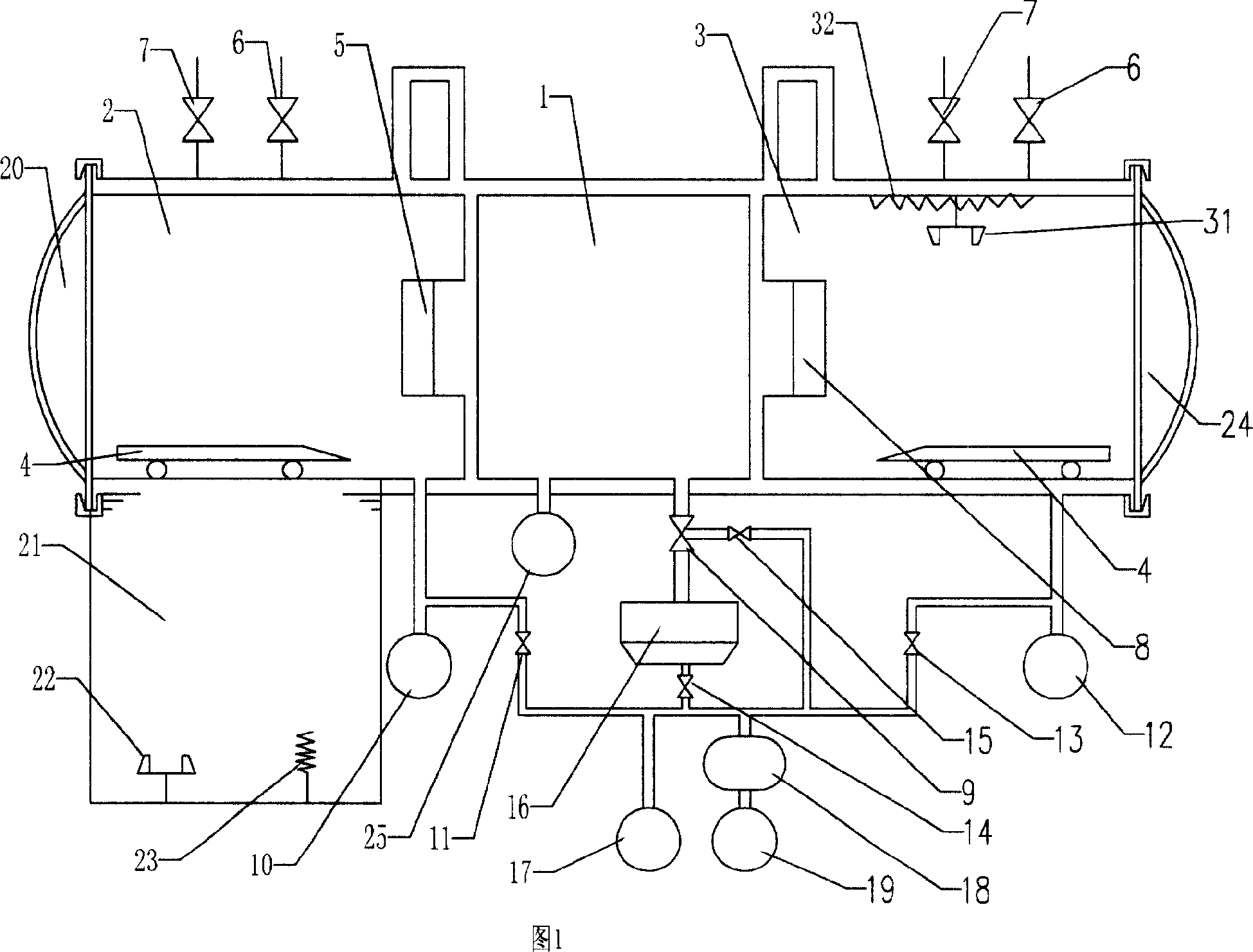
[0024] As shown in Figure 1, the vacuum heat treatment furnace includes a heating chamber 1, an oil quenching chamber 2, a gas quenching chamber 3, an electric control system, a quick transfer device, and an exhaust, gas charging system and cooling system connected to the heating chamber 1 and the cooling chamber The oil quenching chamber 2 and the gas quenching chamber 3 are respectively arranged at both ends of the heating chamber 1, the heating chamber 1 is connected with the oil quenching chamber 2 and the gas quenching chamber 3, and an insulating door 5, which can be opened and closed is arranged between the two. 8. The workpiece car 4 in the quick transfer device can pass through the insulation doors 5 and 8 to reciprocate between the heating chamber 1, the oil quenching chamber 2, and the gas quenching chamber 3. The electronic control system and the workpiece car 4, exhaust and inflation systems, The cooling system and the insulating doors 5, 8 are connected by mechani...

Embodiment 2

[0030] The difference between embodiment two and embodiment one is that the oil quenching is changed to gas quenching, and the operation process is basically the same as the oil quenching operation. That is to say, the workpiece is preheated from the gas quenching chamber 3, passes through the heating chamber 1 and then returns to the gas quenching chamber 3 for gas quenching. When the workpiece car 4 returns to the gas quenching chamber 3 from the high position of the heating chamber 1, close the middle insulation heat 8, and quickly fill in nitrogen gas. Up to 0.5Mpa, the high-pressure high-flow rate cold air circulation quenches the workpiece.

Embodiment 3

[0032] Compared with the first embodiment, the third embodiment differs in that the workpiece is preheated in the gas quenching chamber 3 and oil quenched in the oil quenching chamber 1 . That is to say, the workpiece enters from the gas quenching chamber 3, passes through the heating chamber 1, and then enters the oil quenching chamber 2 for oil quenching. When the workpiece car 4 enters the gas quenching chamber 3, the gas quenching chamber 3 is evacuated, and the heating chamber 1 is evacuated to not less than 1.33Pa. When the workpiece car 4 enters the oil quenching chamber 2 from the heating chamber 1, it is closed. The intermediate heat 5 fills the oil quenching chamber 2 with nitrogen from the inflation valve 7, and the nitrogen pressure is less than or equal to 0.16Mpa; at the same time, the workpiece car 4 is lowered into the oil tank, and the oil agitator 22 is started to oil quench the workpiece. After oil quenching finishes, workpiece car 4 rises, and oil agitator ...


PUM


Abstract

The invention discloses a method and devices of vacuum heat treatment for shear productions. A furnace of heat treatment with three-cell vacuum, a standard closed loop control system and intelligent controlling are adopted to guarantee high craft accuracy. The method can efficiently solve problems of deficient finish and hardness to meet the requirements including sharp cutting edge, non-wearing and non-tipping. Processed by vacuum heat treatment, shears have much strongpoint including non-oxidation, non-decarburizing, good surface craft, minute deforming, excellent integrated mechanical property of heat treatment and long operating life. The method guarantees finish and hardness of shears and meets the requirements of sharp cutting edge, non-wearing and non-tipping. Compared with existing techniques, the method can reduce the power consumption of production, revive partial contradiction of using electricity, reduce cost of productions, advance performance and lifespan of productions, save energy sources and improve efficiency of productions.

Description

technical field [0001] The invention relates to the technical field of heat treatment of knives and scissors, in particular to an integrated vacuum heat treatment device and method for vacuum heating and oil quenching or air cooling of knives and scissors. Background technique [0002] In the production process of knives and scissors, heat treatment is the most critical core technology, which directly affects the product quality of knives and scissors. At present, domestic knives and scissors manufacturers use resistance furnaces for heat treatment, except for a small number of which still use very backward gas-fired furnaces for heating. However, these heat treatment methods have low thermal efficiency, high energy consumption, low control accuracy, and poor product quality. Stable, low-grade knives and scissors produced and other shortcomings. And because in these methods all are directly to knife and scissors product heating in the air, easily cause oxidation and decarbu...

Claims


Application Information

Patent Timeline
Patent Type & Authority Applications(China)
IPC IPC(8): C21D9/18C21D1/58C21D1/613C21D11/00
Inventor 李积回
Owner 李积回
Why Eureka
Try Eureka