Eureka AIR delivers breakthrough ideas for toughest innovation challenges, trusted by R&D personnel around the world.

Fabrication method of photomask-blank

A manufacturing method and technology of photomasks, which are applied in the direction of originals for photomechanical processing, photolithographic process of patterned surfaces, semiconductor/solid-state device manufacturing, etc., can solve the problem of insufficient flatness of photomasks, particle adhesion, Affect the production yield and other issues, to achieve the effect of uniform distribution in the plane

Active Publication Date: 2012-02-01
SHIN ETSU CHEM CO LTD
View PDF2 Cites 0 Cited by
  • Summary
  • Abstract
  • Description
  • Claims
  • Application Information

AI Technical Summary

Problems solved by technology

[0012] On the other hand, as can be seen from the above formula (2), although the reduction of the exposure wavelength is effective for the reduction of the resolvable linewidth RP, it has the problem of causing a reduction in the depth of focus DOF, which in turn adversely affects the Production yield
However, the decrease in exposure wavelength also leads to a decrease in the depth of focus DOF, and thus has the problem that if the flatness of the photomask is insufficient, focus errors are caused, resulting in lower production yields
However, these devices have problems in that the substrate itself is damaged due to an increase in the temperature of the substrate by excessively giving energy, or the productivity is lowered due to prolongation of the processing time.
[0027] However, in the case where processing using a flash lamp is performed as described in prior art document 2, flash irradiation causes generation of particles in the chamber by a mechanism described later, and these particles adhere to the substrate and cannot pass through subsequent cleaning to remove
Therefore, there arises a problem that the number of defects caused by particles in the photomask substrate increases

Method used


Image

  • Fabrication method of photomask-blank
  • Fabrication method of photomask-blank
  • Fabrication method of photomask-blank

Examples


example 1

[0068] (Example 1: Reducing roughness of indoor surfaces)

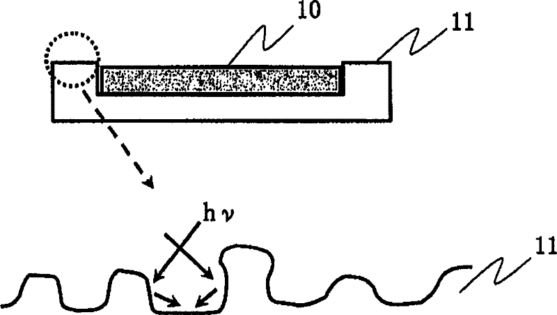
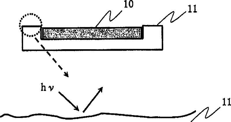
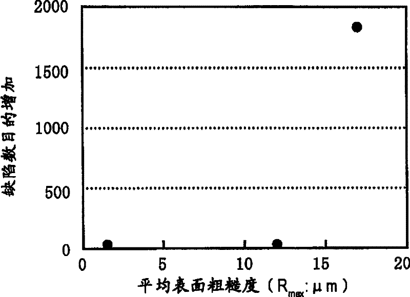
[0069] This example concerns a technique for reducing particle generation during the flash treatment step by reducing the roughness of the chamber surfaces.

[0070] The inventors' studies have demonstrated that when the surface of a jig in a chamber or the inner wall of a chamber is irradiated with a flashlight, multiple reflection etc. cracking, resulting in fine particles.

[0071] In order to prevent partial cracking of the indoor surface due to expansion or contraction of the material of the indoor surface, quartz glass can be effectively used.

[0072] Thus, in the following description, unless otherwise specifically stated, it is assumed that the chamber and the jig such as the susceptor accommodated in the chamber are made of quartz glass. As described in detail below, quartz glass has another advantage: since its transmittance to glints can be easily controlled, the amount of light energy imparted to the su...

example 2

[0101] (Example 2: Study on the pressure in the chamber)

[0102] This example concerns the effect of pressure in the chamber on particle generation during flash exposure.

[0103] It has been demonstrated by the inventors' studies that by reducing the pressure in the chamber where the flash irradiation occurs, the generation of particles can be effectively suppressed.

[0104] According to the prior art, when flash irradiation is performed, once the chamber is evacuated, nitrogen gas is introduced into the chamber through a filter capable of removing, for example, particles of 0.1 μm diameter, and then the cleaned nitrogen gas is flowed at atmospheric pressure Perform flash exposure. However, it has been proved by experiments that if flash irradiation is performed under atmospheric pressure in this way, a large number of defects appear with a certain probability (frequency). The inventors considered this phenomenon as follows.

[0105] Figure 3A and 3B is a diagram illu...

example 3

[0121] (Example 3: Structure of the base 1)

[0122] This example relates to a structure of a susceptor on which a substrate is mounted during flash irradiation, which is intended to reduce particles generated during flash irradiation by minimizing the amount of irradiation light from a flash lamp.

[0123] Figure 6A and 6B is a diagram for explaining the behavior of light from a flash lamp after being vertically incident on a substrate mounted on the susceptor and passing through the substrate with respect to susceptors of different structures. Figure 6A The bases shown in are made of clear quartz only, while Figure 6B The base shown in is made of opaque quartz only.

[0124] The term "pedestal" in this specification is used broadly to refer to a member for holding a substrate (or a member on which the substrate is mounted). Therefore, the shape of the base and the like are not limited to those shown in these drawings. In addition, the quartz glass described as the ba...


PUM

PropertyMeasurementUnit
surface roughnessaaaaaaaaaa

Abstract

PROBLEM TO BE SOLVED: To provide a fabrication method of a photomask-blank that has a reduced number of particle-caused defects. ŽSOLUTION: A susceptor 11 having the most basic structure has a three-layer structure including a first and a second transparent quartz part 11a and an opaque quartz part 11b sandwiched therebetween. For example, the opaque quartz part 11b is made of "foamed quartz". The opacity to flash light is determined to fall within an appropriate range based on the material or thickness of the opaque quartz part 11b, taking into consideration the composition or thickness of a thin film formed on a substrate 10 and various conditions concerning the energy of the irradiation light during flash light irradiation or the like. The stack structure may by composed of a stack of a plurality of opaque quartz layers having different opacities, or of a stack of n layers comprising light transmitting materials (wherein n is a natural number equal to or more than 2), and at least one of the n layers has an opacity different from that of other layers. Ž

Description

technical field [0001] The invention relates to a method for manufacturing a photomask-blank. In particular, the present invention relates to a technique for manufacturing a photomask substrate, which is a base material for photomasks used in semiconductor integrated circuits, charge-coupled devices (CCDs), Fine processing of color filters and magnetic heads of liquid crystal devices (LCD). Background technique [0002] The packaging density of semiconductor integrated circuits is increasing, and the exposure wavelength of exposure equipment used in photolithography for manufacturing semiconductor integrated circuits and the like is becoming shorter and shorter in order to improve resolution. According to the lithography blueprint in the International Semiconductor Technology Blueprint (ITRS) updated in 2004, the main light source is changed from the ultraviolet light source of g light (wavelength λ=436nm) or i light (wavelength λ=365nm) to a shorter wavelength light source...

Claims


Application Information

Patent Timeline
Patent Type & Authority Patents(China)
IPC IPC(8): G03F1/00G03F7/00H01L21/027C23C14/06G03F1/32G03F1/54G03F1/68
Inventor 福岛慎泰吉川博树金子英雄稻月判臣
Owner SHIN ETSU CHEM CO LTD
Why Eureka
Eureka Blog
Learn More