Method for constructing depolarization filter of wide spectrum and 45 degree angle of incidence
A construction method and filter technology, applied in the field of optical filters, can solve problems such as optical performance gap, and achieve the effect of less film layers, easy plating and wide range
Inactive Publication Date: 2007-05-09
SHANGHAI INST OF TECHNICAL PHYSICS - CHINESE ACAD OF SCI
View PDF0 Cites 12 Cited by
- Summary
- Abstract
- Description
- Claims
- Application Information
AI Technical Summary
Problems solved by technology
Therefore, the optical performance of the optical filters currently in use is still far from the ideal requirements. The two indicators of low polarization and high transmission (or high reflection) are often at the expense of each other.
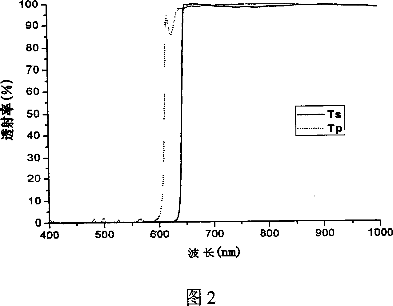
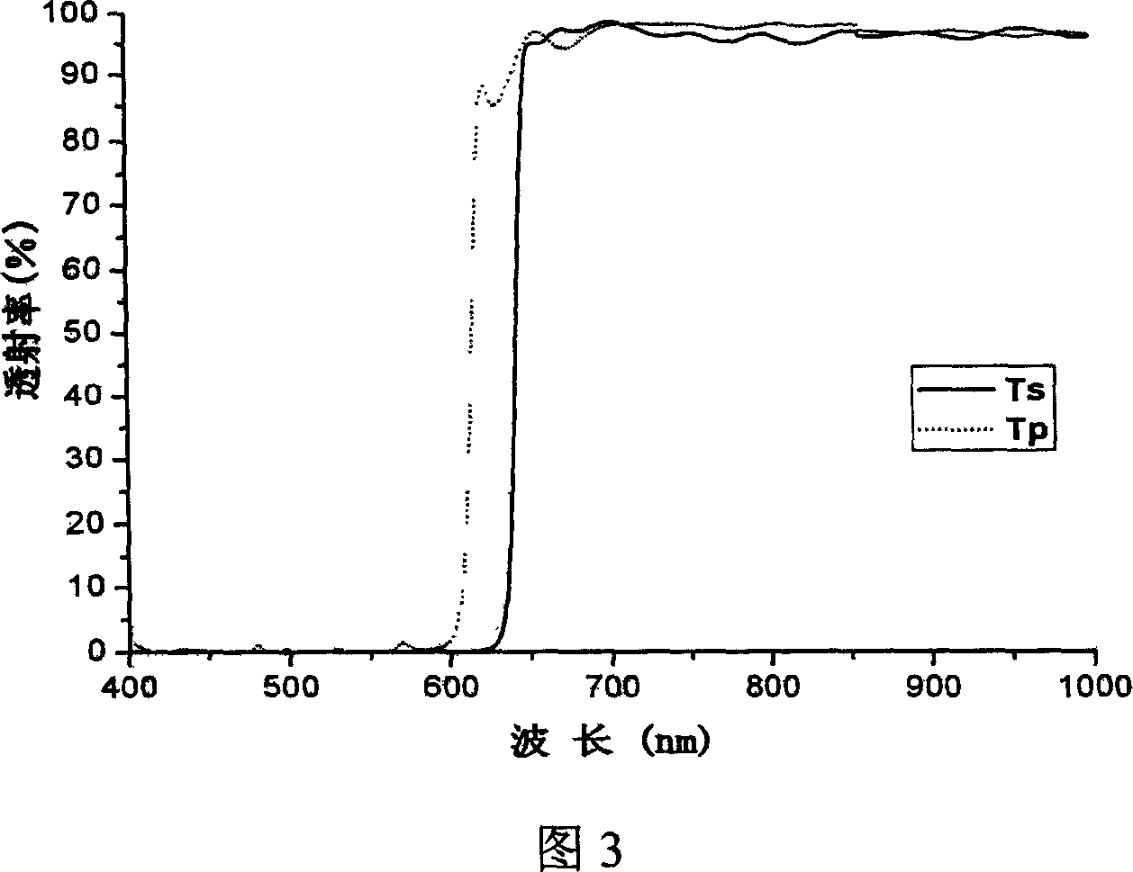
However, there are few studies on the low polarization filter with high reflectivity in the visible range of 400-600nm and high transmittance in the range of 650-1000nm required in the optical path of the multispectral ocean remote sensing instrument system. It is reported that this may be one of the factors limiting the development of marine remote sensing systems
Method used
View moreImage
Smart ImageViewing Examples
Examples
example 2
[0033] The difference between Example 2 and Example 1 is that the high refractive index film material adopts TiO 2 , the low refractive index film material uses Al 2 o 3 , the film thickness distribution of the final film system after optimization is shown in Table 2, and the calculated spectral curve is shown in Figure 4.
[0034] film layer
[0035] film layer
Login to View More PUM
 Abstract
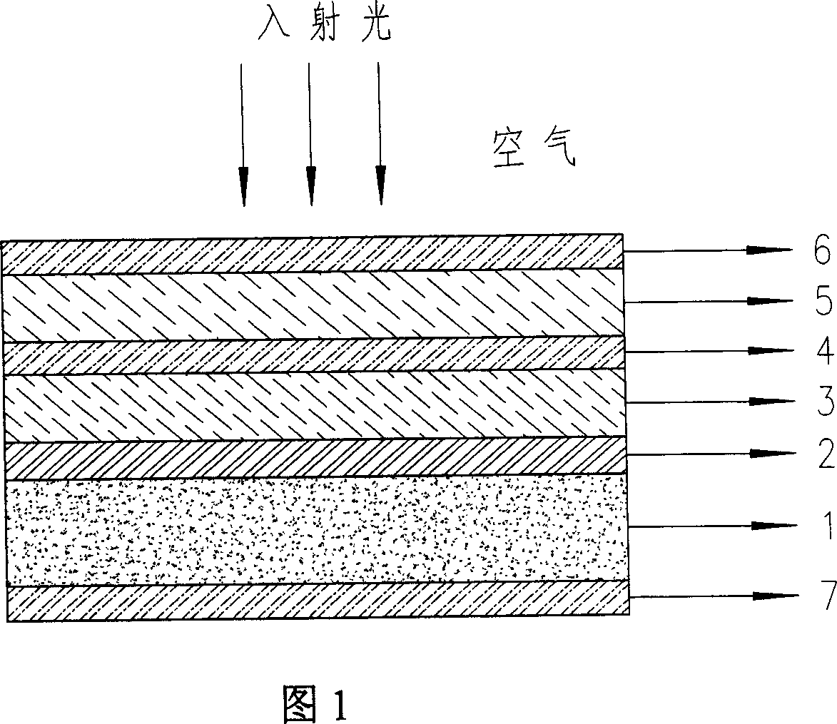
A method for structuring depolarization filter with 45degree incoming wide spectrum includes applying two double-reflection films with different central wavelength to form basic module system by stacking three matching layers then optimizing film layer thickness of basic module system by operating size variation program in module design and analysis software of Tfcalc3.5 in order to obtain final film layer thickness of module system on coated film.
Description
technical field [0001] The invention relates to an optical filter, in particular to a construction method of a 45° incident wide-spectrum depolarizing film filter. Background technique [0002] Thin film filter is one of the important optical components in the optical path of multispectral remote sensing instrument system. It is mostly in the working state of oblique incidence in the optical path of the system, and the oblique incidence of light will bring polarization effects to the transmitted light or reflected light of the system. In addition, many detected spectra are originally polarized spectra, which seriously affects the accuracy of target information. Accurate detection. In order to ensure that the spectroscopic instrument receives accurate target radiation data, the system must be depolarized, and accordingly, the thin-film filter also requires depolarization. [0003] At present, the research on depolarizing filters at home and abroad is mainly concentrated in ...
Claims
Login to View More Application Information
Patent Timeline
 IPC IPC(8): G02B5/20G02B27/00
Inventor 马小凤刘定权陈刚李大琪朱圳张凤山严义勋
Owner SHANGHAI INST OF TECHNICAL PHYSICS - CHINESE ACAD OF SCI
Features
- R&D
- Intellectual Property
- Life Sciences
- Materials
- Tech Scout
- Unparalleled Data Quality
- Higher Quality Content
- 60% Fewer Hallucinations
Learn More Browse by: Latest US Patents, China's latest patents, Technical Efficacy Thesaurus, Application Domain, Technology Topic, Popular Technical Reports.
© 2025 PatSnap. All rights reserved.Legal|Privacy policy|Modern Slavery Act Transparency Statement|Sitemap|About US| Contact US: help@patsnap.com


