H surface substrate integrated waveguide ring-shape bridge

A substrate-integrated waveguide and ring technology, applied in waveguide-type devices, circuits, electrical components, etc., can solve the problems of reduced system performance, high cost, electromagnetic interference, etc., and achieve easy integration, low production cost, and short purchase cycle. Effect

Inactive Publication Date: 2007-06-06
SOUTHEAST UNIV
View PDF0 Cites 7 Cited by
  • Summary
  • Abstract
  • Description
  • Claims
  • Application Information

AI Technical Summary

Problems solved by technology

The early hybrid ring was made of waveguide, with large power capacity, suitable for radar antenna transceiver switch, but it has the disadvantages of large volume, bulky, expensive and difficult to integrate [1]-[5]
Compared with the bridge with waveguide structure, the bridge composed of microstrip lines that can transmit quasi-TEM waves has the advantages of compact structure, small size, light weight, wide frequency band and easy manufacture. [6]-[11] ; But there are problems such as radiation loss and electromagnetic interference, and the discontinuity generated by the connection between the microstrip line ring bridge and the substrate integrated waveguide device will reduce the performance of the system

Method used


Image

  • H surface substrate integrated waveguide ring-shape bridge
  • H surface substrate integrated waveguide ring-shape bridge
  • H surface substrate integrated waveguide ring-shape bridge

Examples


Embodiment Construction

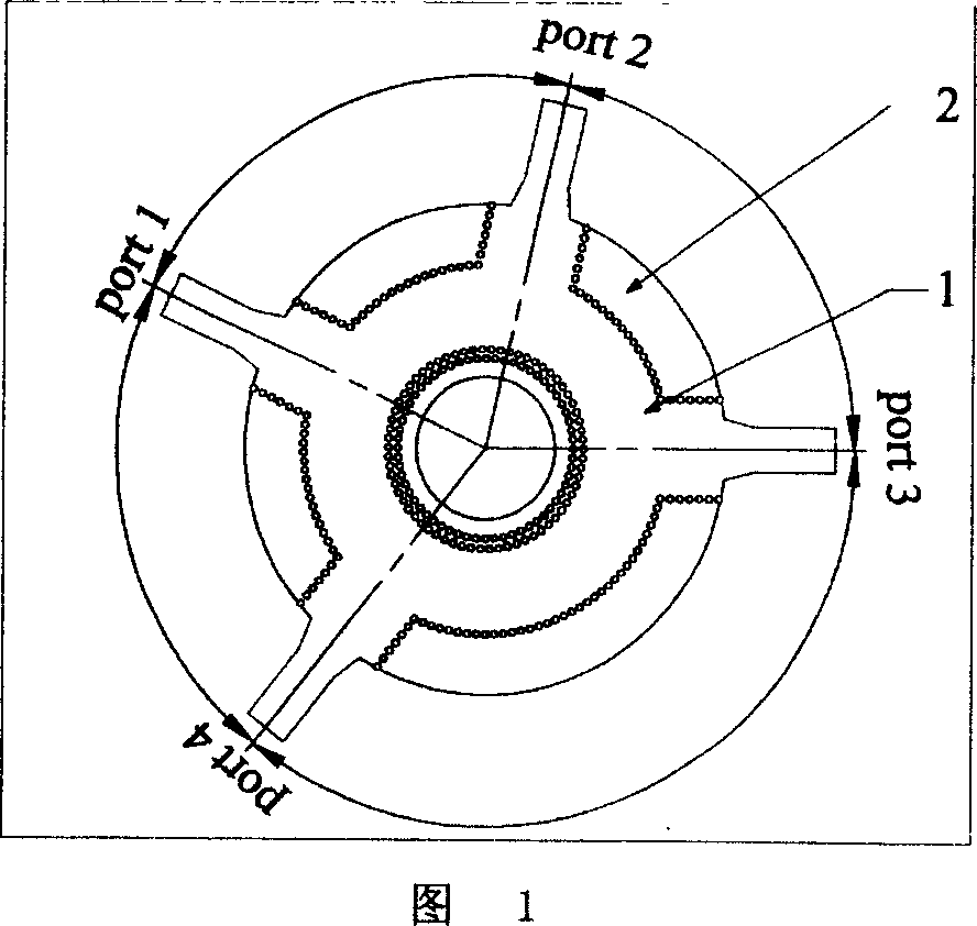
[0016] Referring to FIG. 1 , an H-plane substrate integrated waveguide ring bridge applied to microwave and millimeter wave circuits includes: a ring waveguide structure 1, and a non-inverting input port1 and an inverting input port2 are provided on the ring waveguide structure 1 and two output ports port3 and port4, the ring waveguide structure 1 is composed of metallized through holes arranged in a coaxial circle, and the metallized through holes are arranged on the dielectric substrate 2 coated with metal foil on both sides.

[0017] With reference to Fig. 4, the metallized through-hole is arranged on the dielectric substrate 2 that is covered with metal foil on both sides to set the through hole, and the metal bushing 3 is set in the through hole and the metal bushing 3 is covered with the metal on the dielectric substrate 2. foil connection.

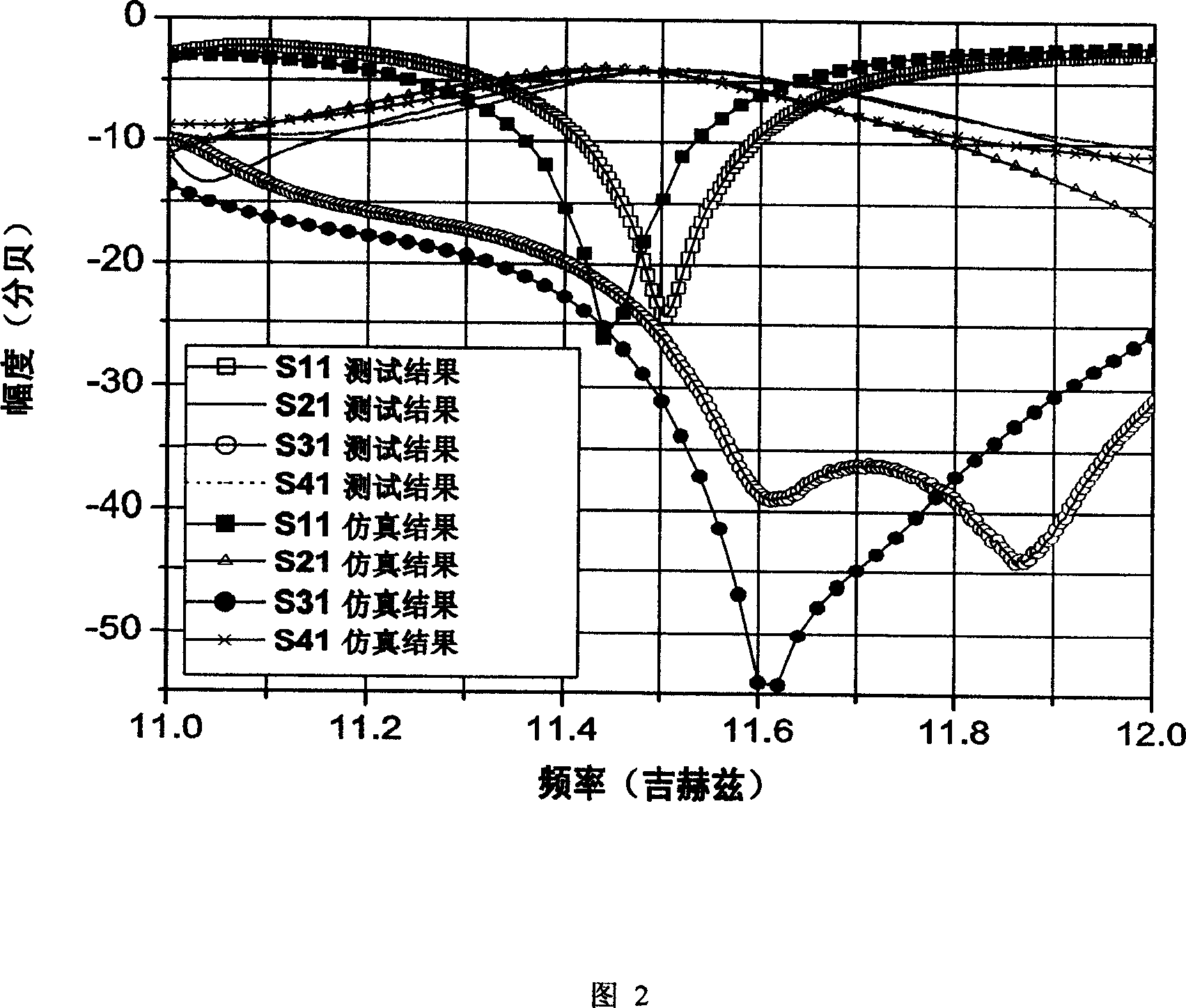
[0018] Referring to FIG. 2 , this figure shows the simulation results and test results of the scattering parameters excited by por...


PUM


Abstract

A ring type of bridge with waveguide integrated by H numbers of substrate is prepared as forming a ring waveguide structure by metalized through-holes being arranged in coaxial circle way, setting same-phase input end and reverse-phase input end as well as two output ends on ring waveguide structure, arranging metalized through-holes on media substrate coated with metal foil on both surfaces, enabling to use SIW as lead out arm of port for connecting said bridge to SIW components such as SIW antenna.

Description

technical field [0001] The invention relates to an annular electric bridge, in particular to an H-plane substrate integrated waveguide annular electric bridge. Background technique [0002] The ring bridge (also known as the hybrid ring) is a key component of the microwave and millimeter radio frequency subsystem, and is widely used in microwave circuits to realize the functions of power distribution and obtaining a certain amplitude and phase relationship between signals. The early hybrid ring was made of waveguide, with large power capacity, suitable for radar antenna transceiver switch, but it has the disadvantages of large volume, bulky, expensive and difficult to integrate [1]-[5] . Compared with the bridge with waveguide structure, the bridge composed of microstrip lines that can transmit quasi-TEM waves has the advantages of compact structure, small size, light weight, wide frequency band and easy manufacture. [6]-[11] ; But there are problems such as radiation loss...

Claims


Application Information

Patent Timeline
Patent Type & Authority Applications(China)
IPC IPC(8): H01P1/38H01P1/39
Inventor 张玉林洪伟吴柯颜力
Owner SOUTHEAST UNIV
Why Eureka
Try Eureka