
Remanent electron beam absorbent radiation device

An irradiation device and electron beam technology, applied in the field of radiation processing, can solve problems such as damage, high pressure and high heat area, poor thermal conductivity, etc., and achieve the effects of preventing local accumulation, reducing output, and saving costs

Active Publication Date: 2007-07-04
TSINGHUA UNIV +1
View PDF0 Cites 7 Cited by
  • Summary
  • Abstract
  • Description
  • Claims
  • Application Information

AI Technical Summary

Problems solved by technology

However, the open water tank is not suitable for mobile irradiation equipment, and carbon-doped engineering plastics have poor electrical and thermal conductivity. In high-power electron beam irradiation equipment, the local charge and heat accumulation in a short period of time is very large, and it is easy to form high voltage. High heat zone, very destructive

Method used


Image

  • Remanent electron beam absorbent radiation device
  • Remanent electron beam absorbent radiation device

Examples


Embodiment 1

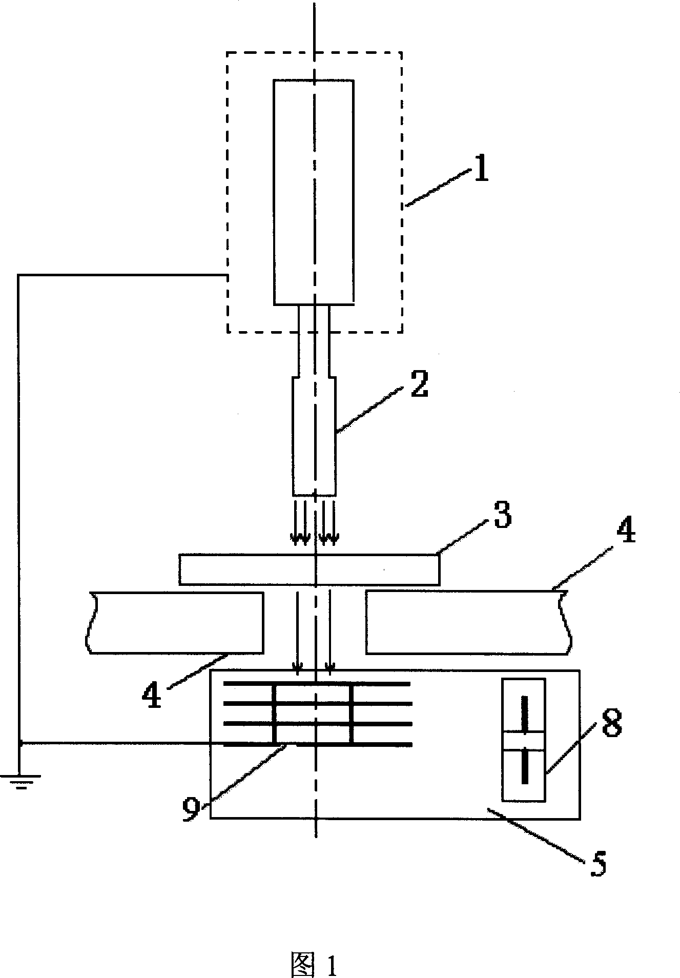
[0013] Referring to Fig. 1, the irradiation device of the present invention comprises an electron linear accelerator 1, an electron beam drift scanning frame 2 connected with the electron beam linear accelerator 1, and a mechanical transmission mechanism placed under the electron beam drift scanning frame 2 and capable of placing an irradiated object 3 4. An electron beam absorber 5 is placed directly under the electron beam drifting scanning frame 2 and at the bottom of the mechanical transmission mechanism 4 . The electron beam absorber 5 and the electron linear accelerator 1 are connected by wires to form an electronic circuit. The electron beam absorber 5 is made of an absorbing seat 9 with cooling fins made of aluminum material and a fan 8 placed beside the absorbing seat 9 to form. The wind generated by the blower fan 8 radiates heat to the absorbing seat 9, and simultaneously, ozone can be eliminated. The present invention can not only effectively reduce the output of...

Embodiment 2

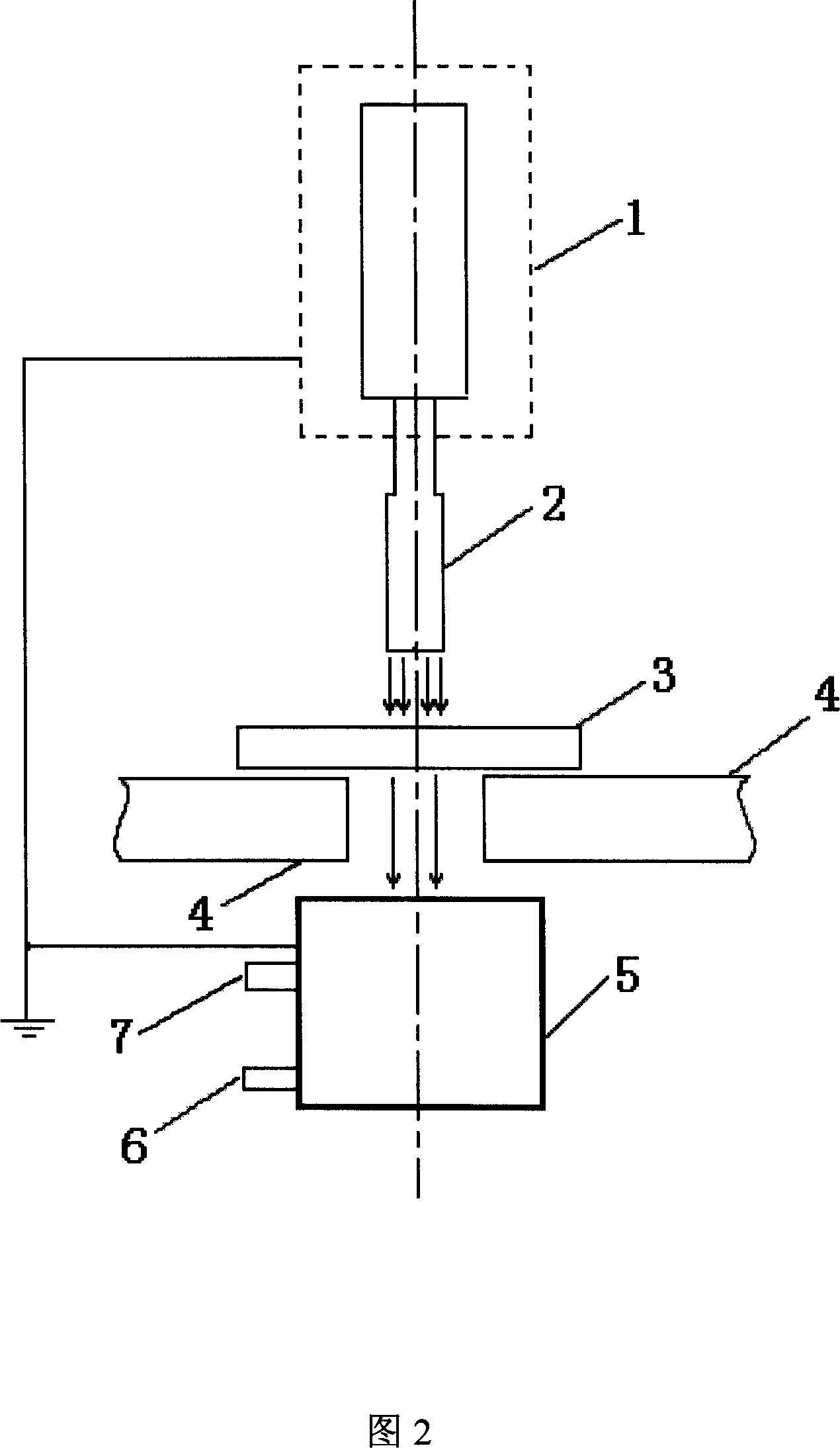
[0015] Referring to Fig. 2, the irradiation device of the present invention includes an electron linear accelerator 1, an electron beam drift scanning frame 2 connected with the electron beam linear accelerator 1, a mechanical transmission mechanism placed under the electron beam drift scanning frame 2 and capable of placing an irradiated object 3 4. An electron beam absorber 5 is placed directly under the electron beam drifting scanning frame 2 and at the bottom of the mechanical transmission mechanism 4 . The electron beam absorber 5 and the electron linear accelerator 1 are connected by wires to form an electronic circuit. The electron beam absorber 5 is made of aluminum material with a sealed box structure, and the box is provided with a water inlet 6 and a water outlet 7, and the electron beam absorber 5 is cooled by connecting with an external water cooling system. The invention can not only effectively reduce the output of X-rays, but also prevent the remaining electro...


PUM


Abstract

The invention discloses an irradiation plant which can absorb residual electron beam that belongs to fields of radiation processing technology. It includes electron linear accelerator, electron beam drift scanning bracket which is connected with electron linear accelerator, mechanical transport mechanism which is mounted below the electron beam drift scanning bracket and on which the object to be irradiated is placed. It characterized in that an electron beam absorber is mounted just below the electron beam drift scanning bracket and at the bottom of the mechanical transport mechanism. The electron beam absorber and the electron linear accelerator are connected by leads to form an electronic loop to conduct heat. With this invention, the thickness of the inoxidizing coating in electron beam irradiation plant can be decreased, the cost can be saved, and the volume and weight can also be decreased, the local cumulation of charge and quantity of heat can be prevented to realize the self-sield and miniaturization of the electron beam irradiation plant, the applied range of the electron beam irradiation plant can be extended further more.

Description

technical field [0001] The invention relates to the technical field of radiation processing, in particular to an irradiation device using an electron beam accelerator as a radiation source. Background technique [0002] Electron beam irradiation treatment technology is a treatment technology that uses the ionization ability and bremsstrahlung effect of electron beams to cause certain biological and physical effects on the irradiated items, thereby performing sterilization and deworming or changing the physical properties of the items. In the prior art, accelerators are generally used to generate electron beams with a certain energy, which are drawn out by titanium windows. These accelerators include: traveling wave or standing wave electron linear accelerators, DC high-voltage accelerators, high-frequency high-voltage accelerators, etc. The irradiated article is passed through the electron beam area led by the titanium window at a uniform speed by the mechanical transmission...

Claims


Application Information

Patent Timeline
Patent Type & Authority Applications(China)
IPC IPC(8): G21K5/00
Inventor 唐华平刘耀红张东生阎忻水高建军高峰刘晋升贾玮印炜张丹谷冲
Owner TSINGHUA UNIV
Learn More