Microwave device and flow tube used therein

a flow tube and microwave technology, applied in the field of microwave devices and flow tubes, can solve the problems of limited throughput capacity of the batch processing device, achieve the effects of improving treatment efficiency, increasing liquid volume, and reducing the average strength of electric fields

Inactive Publication Date: 2018-10-02
PACIFIC MICROWAVE TECH
View PDF24 Cites 0 Cited by
  • Summary
  • Abstract
  • Description
  • Claims
  • Application Information

AI Technical Summary

Benefits of technology

[0012]A flow tube according to an aspect of the present invention includes an obstacle which has a dielectric constant differing from that of a liquid to be treated and disturbs the flow of the liquid to be treated. If the flow tube is installed in an irradiation chamber (resonant cavity) of a microwave device, since the distribution of an electric field in the flow tube through which the liquid to be treated flows becomes non-uniform, so that an average strength of the electric field is reduced. Accordingly, the absorption of a microwave by the liquid to be treated is inhibited. As a result, even if the volume of the liquid to be treated present in an irradiation chamber is enlarged by making the diameter of the flow tube larger, the rate of reduction of the resonance frequency is inhibited. Therefore, it can be easily achieved to maintain the resonance frequency for various kinds of liquid to be treated within a predetermined band, for example, the Industry-Science-Medical (ISM) band. In addition, since a decrease of Q is inhibited, a synchronization can be easily made, so that treatment efficiency can be improved by increasing the volume of the liquid to be treated present in the irradiation chamber.
[0013]Regarding a microwave device in another aspect of the present invention, in an irradiation chamber (resonant cavity) of a cavity resonator thereof, an electric field is generated in parallel to a center axis of the irradiation chamber. A flow tube in the irradiation chamber is provided in a helical fashion winding around the center axis of the irradiation chamber and thus, a liquid to be treated flowing through the flow tube flows in a direction crossing the electric field. With this structure, a boundary of the liquid to be treated, that is, a dielectric material is aligned in a direction crossing the electric field and thus, energy absorbed by the liquid to be treated per unit time is reduced and decrease in Q is inhibited. Therefore, even if the flow rate of the liquid to be treated is increased by using a larger diameter flow tube than in the conventional case, the decrease in Q becomes significantly mild and Q can be kept at an appropriate value. By adopting the flow tube in a helical fashion, when compared with a straight flow tube, the flowing distance of the liquid to be treated in the irradiation chamber is elongated, and hence the residence time in the irradiation chamber can be gained while the strength of a microwave received by the liquid to be treated being maintained constant. As a result of the foregoing, uniform and efficient treatment by a single-mode cavity resonator can be achieved.

Problems solved by technology

However, the batch processing device is limited in throughput capacity and thus, a flow type device in which a flow channel is formed and irradiated with a microwave while a liquid to be treated flows therethrough is under study (see Patent Document 1).

Method used


Image

  • Microwave device and flow tube used therein
  • Microwave device and flow tube used therein
  • Microwave device and flow tube used therein

Examples


first embodiment

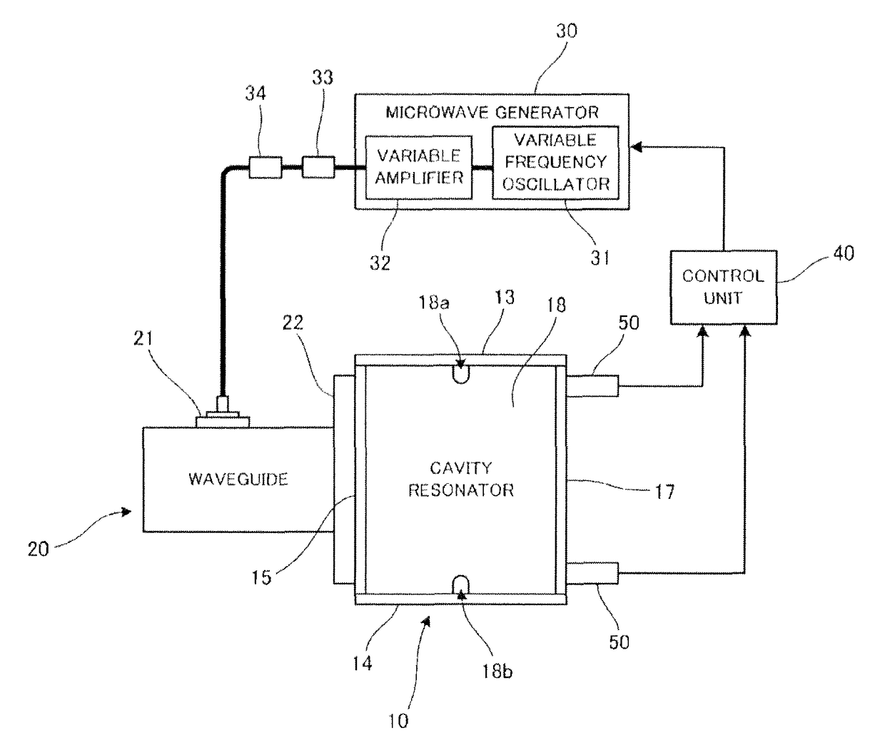
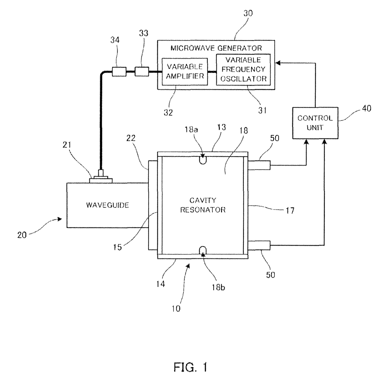
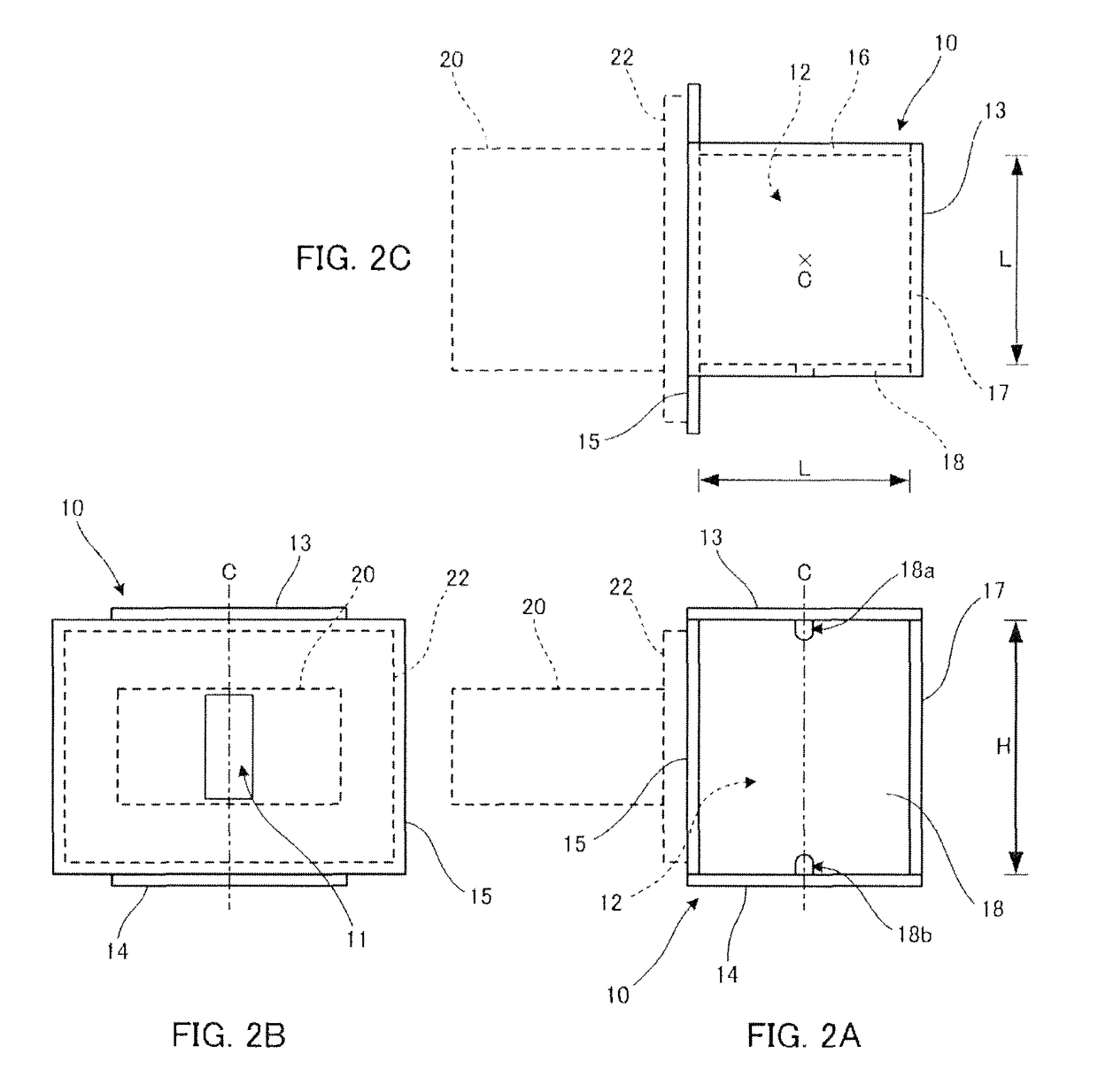
[0045]the cavity resonator 10 in a microwave device as described above is shown in FIG. 2.

[0046]The cavity resonator 10 in the first embodiment includes top and bottom walls 13, 14 and rectangular sidewalls 15, 16, 17, 18. As shown in FIG. 2, the mutually opposite top and bottom walls 13, 14 arranged one above the other are approximately square. Each of the rectangular sidewalls 15, 16, 17, 18 is fixed to each side of the top and bottom walls 13, 14 by bolts or the like. In the first embodiment, one sidewall 15 shown in FIG. 2B of the four sidewalls 15, 16, 17, 18 has a larger area corresponding to a flange 22 of the waveguide 20 to be connected with the waveguide 20 and enlarged portions thereof protrude from edges of the top and bottom walls 13, 14. Also, one sidewall 18 shown in FIG. 2A of the four sidewalls 15, 16, 17, 18 has flow tube insertion ports 18a, 18b provided at edges abutting the top and bottom walls 13, 14.

[0047]The irradiation chamber 12 is formed inside the cavity ...

second embodiment

[0056]The support rod 61 or 61′ may be formed of alumina (aluminum oxide) whose microwave loss is small and which is superior in thermal conductivity. If the support rod 61 or 61′ is made of alumina, heat of a liquid to be treated present in a downstream portion of the flow tube 60 can be conducted to a liquid to be treated present in an upstream portion of the flow tube 60, and hence a uniform temperature property of the liquid to be treated flowing through the flow tube 60 can be improved because of the good thermal conduction. The temperature of the liquid to be treated becomes higher in the downstream portion than in the upstream portion due to heating involved in microwave irradiation. However, the uniform temperature property required from a chemical reaction can be improved by conducting the heat to the upstream portion via the support rod 61 or 61′. For the support rod 61′ in the second embodiment, a channel 61b′ cutting through in the axial direction is internally formed an...

third embodiment

[0089]a cavity resonator in a microwave device as described above is shown in FIG. 13.

[0090]The cavity resonator 110 in the third embodiment includes two top and bottom walls 113, 114 and rectangular sidewalls 115, 116, 117, 118. As shown in FIG. 13, the mutually opposite top and bottom walls 113, 114 arranged one above the other are approximately square. Each of the rectangular sidewalls 115, 116, 117, 118 is fixed to each side of the top and bottom walls 113, 114 by bolts or the like. In the present embodiment, one sidewall 115 shown in FIG. 13B of the four sidewalls 115, 116, 117, 118 has a larger area corresponding to a flange 122 of the waveguide 120 to be connected with the waveguide 120 and enlarged portions thereof protrude from edges of the top and bottom walls 113, 114.

[0091]The irradiation chamber 12 is formed inside the cavity resonator 110 in the shape of a rectangular solid formed by assembling the top and bottom walls 113, 114 and the sidewalls 115, 116, 117, 118. The...


PUM

PropertyMeasurementUnit
frequencyaaaaaaaaaa
diameteraaaaaaaaaa
frequencyaaaaaaaaaa

Abstract

A microwave device includes a microwave generator generating a microwave and outputting the microwave, a waveguide guiding the microwave output from the microwave generator, a cavity resonator, and a flow tube. In some embodiments, the cavity resonator has an irradiation chamber as a quadrangular prism cavity into which the microwave guided by the waveguide is introduced, resonates the microwave in the irradiation chamber, and generates an electric field in TM110 mode along a direction of a center axis through centers of top and bottom faces of the irradiation chamber. The flow tube is installed in the irradiation chamber and formed in a helical fashion by winding and extending around the center axis, and causes a liquid to be treated to flow in a direction crossing the electric field generated in the irradiation chamber. The center axis is a location where the electric field is the strongest in the irradiation chamber.

Description

TECHNICAL FIELD[0001]The present invention relates to an apparatus that treats a substance by irradiating a microwave to heat it or accelerate a chemical reaction thereof, etc.BACKGROUND ART[0002]In recent years, the fact that a microwave accelerates a chemical reaction was found and interest in a chemical reactor using a microwave is increasing in fields such as biochemistry. A batch processing device, for example, a kind of kitchen type microwave oven, is currently mainstream device in such a microwave apparatus for accelerating a chemical reaction or heating, the batch processing device performs a treatment by using a test tube or a flask containing a liquid to be treated. However, the batch processing device is limited in throughput capacity and thus, a flow type device in which a flow channel is formed and irradiated with a microwave while a liquid to be treated flows therethrough is under study (see Patent Document 1).CITATION LISTPatent Document[0003]Patent Document 1: Japane...

Claims


Application Information

Patent Timeline
Patent Type & Authority Patents(United States)
IPC IPC(8): H05B6/64B01J19/12H05B6/80C02F1/30
CPCH05B6/6402B01J19/126H05B6/806B01J2219/0877B01J2219/0892B01J2219/126C02F1/302B01J2219/1227B01J2219/1275B01J2219/1281B01J2219/1284B01J2219/1293B01J2219/1215
Inventor SAIDA, HISATOODAJIMA, HIROMICHIOHNEDA, NORIYUKIYOKOZAWA, SAORI
Owner PACIFIC MICROWAVE TECH
Why Eureka
Try Eureka