Gas jet injector reactor for catalytic fast pyrolysis process

a technology of catalytic pyrolysis and injector reactor, which is applied in the direction of biofuels, waste based fuels, hydrocarbon oil treatment products, etc., can solve the problems of char formation, low yield of aromatics and olefins, and very rapid heating of biomass

Active Publication Date: 2018-10-09
ANELLOTECH INC
View PDF52 Cites 2 Cited by
  • Summary
  • Abstract
  • Description
  • Claims
  • Application Information

AI Technical Summary

Benefits of technology

[0015]The present invention comprises a novel feed system for introducing biomass into a pyrolysis reactor, such as a catalytic fast pyrolysis (CFP) fluid bed reactor, that employs a jet stream of gas or vapor to inject the biomass particles into the fluid bed. The biomass is kept relatively cool, can be metered upstream of a gas jet, and can be injected far into the fluid bed. Good mixing between the relatively cooler biomass with the hot catalyst and other materials in the fluid bed can be insured by adjustment of the number, size, angle, position, and flow rate of the multiple injector ports in larger reactors. The invention may further comprise an automated feed metering system comprising pinch valves and a holding tank that allows operation of the CFP process at higher pressure while allowing the feed to be maintained at lower pressures and injects the biomass in discrete portions that penetrate further into the reactor enhancing mixing and rapid heating of the biomass.
[0019]An advantage of the inventive methods and systems is improved yield of aromatics; preferably the carbon percent yield of aromatics plus olefins is at least 15%, at least 20%, at least 25%, at least 30%, or at least 35%. In some preferred embodiments, the carbon percent yield of para- and meta-xylene is at least 0.5%, at least 1.0%, at least 1.5%, at least 2.0%, or at least 2.5%. In some preferred embodiments, the carbon percent yield of methane is less than 10%, less than 5%, less than 4%, less than 3%, less than 2% or less than 1.5%.

Problems solved by technology

Thus, a problem in the fast pyrolysis and catalytic fast pyrolysis of biomass is how to introduce the biomass feed into the pyrolysis reactor, keeping it from heating prematurely in the feed line where char can form and yet heating it very rapidly once it enters the reaction zone.
Screw auger feed devices have been used to feed the biomass to fluidized bed reactors, but the linear flow rate of the biomass is relatively slow in the feed auger, so the biomass can be heated as it approaches the hot catalyst bed, resulting in char formation and low yields of aromatics and olefins.
Premature partial pyrolysis of the biomass also releases oily intermediates that can clog the movement of the auger.
Scale up of the auger feed system is problematic as well since an auger that extends into the center of a large reactor would necessarily become quite hot or would require cooling that wastes heat and cools the reactor bed.
Bartek in U.S. Pat. No. 8,523,496 describes a process for feeding biomass to a reactor for conversion to oxygenated hydrocarbons that utilizes a spool piece adapted to convey solids from a lower pressure to a higher pressure; however, other than increasing pressure, no steps are taken to control injection conditions or reduce preheating of the biomass.

Method used


Image

  • Gas jet injector reactor for catalytic fast pyrolysis process
  • Gas jet injector reactor for catalytic fast pyrolysis process
  • Gas jet injector reactor for catalytic fast pyrolysis process

Examples


examples 3 through 12

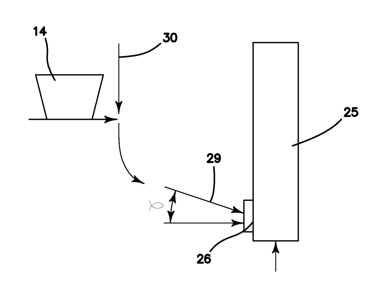
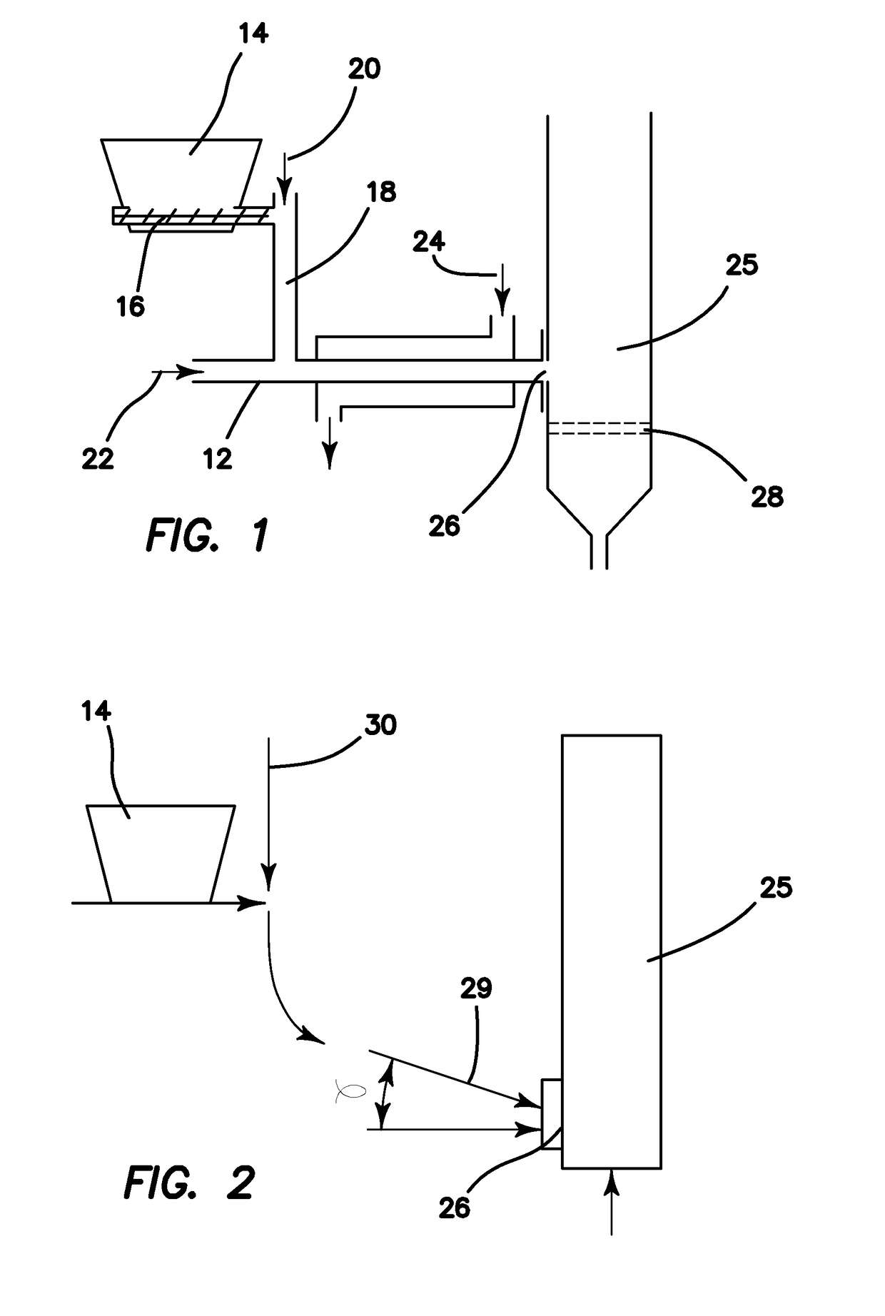
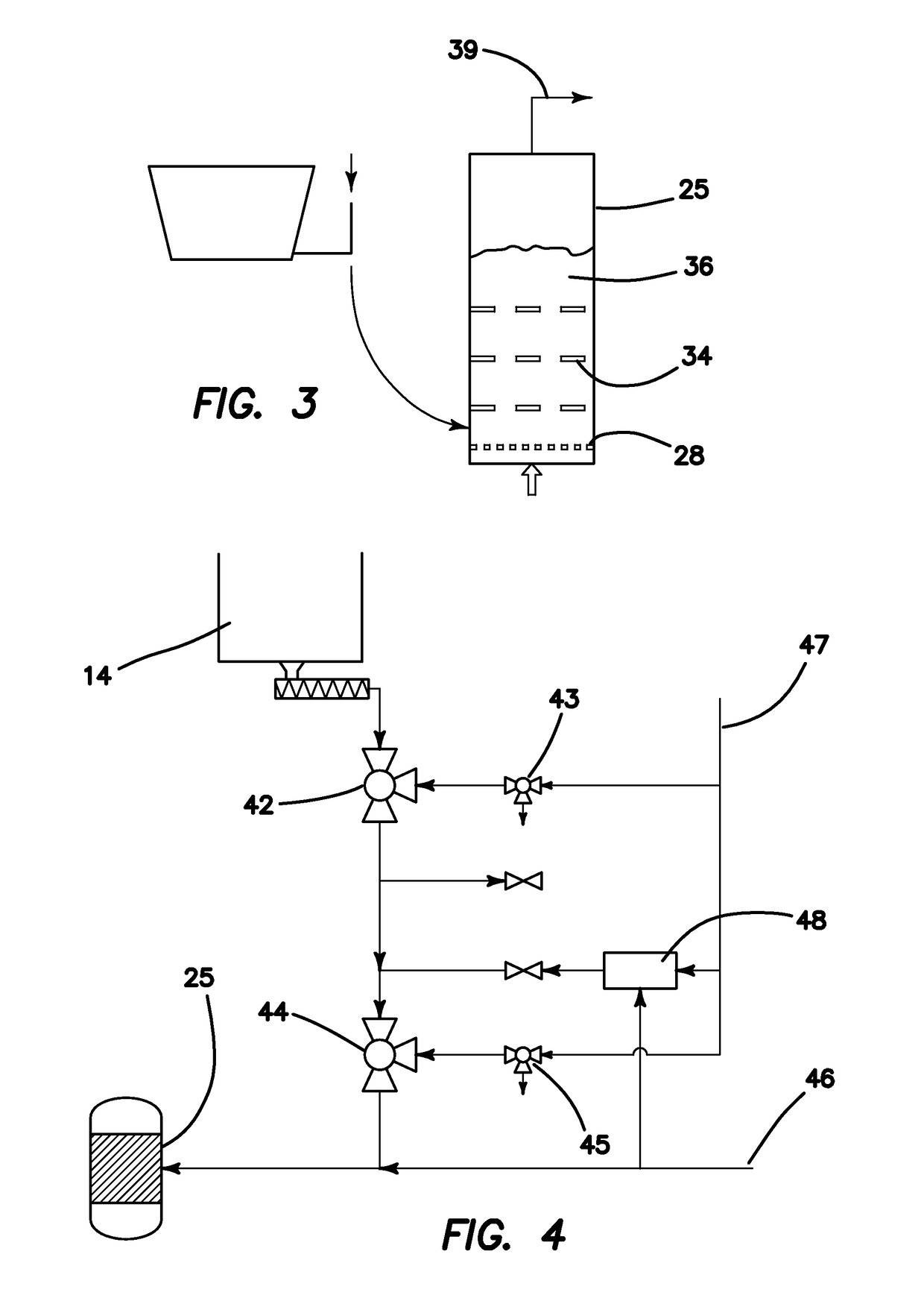
[0094]The biomass transfer tube was replaced by a curved 0.25-inch OD SS-316 tube extending from the feed hopper to the biomass inlet port. The feed hopper was situated above and to the side of the reactor. The angle of entry of the feed tube into the fluid bed was 26 degrees from the horizontal, as shown in FIG. 2. A series of sieve trays made of perforated 316 stainless steel with one-eighth (0.125) inch openings and 42% open area were installed inside the reactor, as shown in FIG. 3. There were six sieve trays attached to a central, threaded rod and there was a 1-inch spacing between the sieve trays.

[0095]A series of experiments was conducted with the conditions as summarized in Table 1.

[0096]As shown in Table 1 (for example, compare examples 9 and 10 with 11 and 12), the ratio of injection flow rate (which is measured at the interface between the injection tube and the reactor, in other words, at the solids inlet to the reactor) to fluidization flow rate (measured at the fluidiz...

example 13

[0100]The reactor of Example 12 that utilized a gas jet injector feed in a 2-inch diameter nominal pipe reactor was charged with 158 g of Catalyst A, a commercially obtained fluid bed ZSM-5 catalyst containing approximately 40 weight % crystalline ZSM-5 in an inert binder. The feed gas flow rate, biomass feed rate, and temperatures were adjusted as shown in Table 2. Ground hardwood pellets containing 46.99% carbon and 6.16% hydrogen were used as the biomass feed. The results show that a high yield of aromatics and olefins can be achieved with an injection velocity of 69 cm / sec and a normalized feed temperature of 150° C. when a gas jet biomass feed system is used.

example 14

[0101]The reactor of Example 13 was charged with 161 g of Catalyst A and the experiment was repeated. The results demonstrate that the process is highly reproducible using a gas jet injector system.


PUM

PropertyMeasurementUnit
linear velocityaaaaaaaaaa
residence timeaaaaaaaaaa

Abstract

Methods and systems utilizing gas jets to carry biomass into a biomass conversion reactor are described. Reactor configurations and conditions for carrying out processes utilizing the gas jets are also described. The use of gas jets has been found to be especially desirable for operation with pyrolysis of biomass in catalytic fluidized bed reactors.

Description

RELATED APPLICATIONS[0001]This application claims the benefit of the priority of U.S. Provisional Patent Application Ser. No. 61 / 755,358, filed 22 Jan. 2013.FIELD OF INVENTION[0002]This invention relates to methods for the production of biochemicals such as biofuel, aromatics, and olefin compounds, and more specifically, to process feed methods, systems, and apparatus for the production of fuels and chemicals via catalytic fast pyrolysis.BACKGROUND[0003]Biomass upgrading requires the feeding of a variety of particulate solid materials such as wood chips, sawdust, yard waste, cuttings, other vegetation; agricultural products and agricultural waste (e.g., corn stover, bagasse, fruit, garbage, silage, etc.); energy crops (e.g. switchgrass, miscanthus); algae and other marine plants; metabolic wastes (e.g., manure, sewage); and cellulosic urban waste etc., to a fluidized bed of catalyst for catalytic fast pyrolysis. Partially upgraded or converted biomass, such as pyrolysis oils, carboh...

Claims


Application Information

Patent Timeline
Patent Type & Authority Patents(United States)
IPC IPC(8): C07C1/00C10G1/08B01J6/00C10B49/10C10B53/02C10B57/06C10G2/00B01J8/18B01J8/00
CPCC10G1/08B01J8/0025B01J8/0045B01J8/1872C10B49/10C10B53/02C10B57/06C10G2/32B01J6/008Y02P30/20B01J2208/0084B01J2208/00176B01J2208/00212B01J2208/00292B01J2208/00548B01J2208/00557B01J2208/00752B01J2208/00938C10G2300/1011C10G2400/30Y02E50/13Y02E50/14Y02E50/32Y02P20/145Y02E50/10Y02E50/30
Inventor MAZANEC, TERRY J.WHITING, JEFFREY P.SONG, RUOZHIGOODMAN, ZACHARY W.SCHMIDT, COLLIN
Owner ANELLOTECH INC
Why Eureka
Try Eureka