
Microscale plasma separator

a plasma separator and micro-scale technology, applied in the field of micro-scale plasma separators, can solve the problems of affecting the use of microfluidic-based systems, requiring special training, and requiring bulky and specially trained personnel, and achieves the effects of simplifying and accelerating the use of such platforms, and reducing the number of samples

Active Publication Date: 2018-10-23
WAINAMICS INC
View PDF33 Cites 2 Cited by
  • Summary
  • Abstract
  • Description
  • Claims
  • Application Information

AI Technical Summary

Benefits of technology

The invention provides a new approach to plasma separation that overcomes the limitations of current systems. The device uses a set of optimized filter materials with a range of pore sizes to construct a multi-stage filtration maze. Chemically induced cell aggregation is used to allow efficient removal of all blood cells in 1-2 minutes, without power or additional instrumentation. The device is compact, simple-to-use, and low-cost disposable, and can be used with various point-of-care testing devices. The device allows users to quantitatively measure the amount of blood sample and can force all blood samples through the membrane leaving zero-dead volume of unprocessed sample. The invention also provides multi-stage filtration in combination with chemically induced aggregation to significantly reduce clogging problems and enable separation of large amounts of blood in a short time.

Problems solved by technology

However, sample preparation steps such as rapid separation of plasma from whole blood is still a challenge that the platform developers have to face.
Current standard requires use of laboratory centrifugation instrument, which is bulky and entails specially trained personnel.
There are several unique challenges associated with the development of a standalone blood-plasma separator for VL testing in resource-limited settings.
Such volumes are large on the microfluidic scale and pose a significant challenge to many microfluidic-based systems.
A third challenge is to carry out plasma separation without lysing cells in the sample which could release contaminating molecules that would complicate or interfere with desired measurements.
A fourth challenge is loss of sample through dead volumes in chambers, filters and passages of POC devices.
Finally, the requirements for portability, safety and ease of use by personnel without extensive training, and the need to function without electricity impose additional restrictions to any platform under consideration for POC use in resource-limited clinical settings.
However, many of these technologies still require electric pumps for flow control and additional blood dilution steps, or they are constrained by small blood volume throughput, long separation time, and lack of efficiency.

Method used


Image

  • Microscale plasma separator
  • Microscale plasma separator
  • Microscale plasma separator

Examples


example 1

Cylindrical Plunger-Actuated Microscale Plasma Separation (MPS) Device

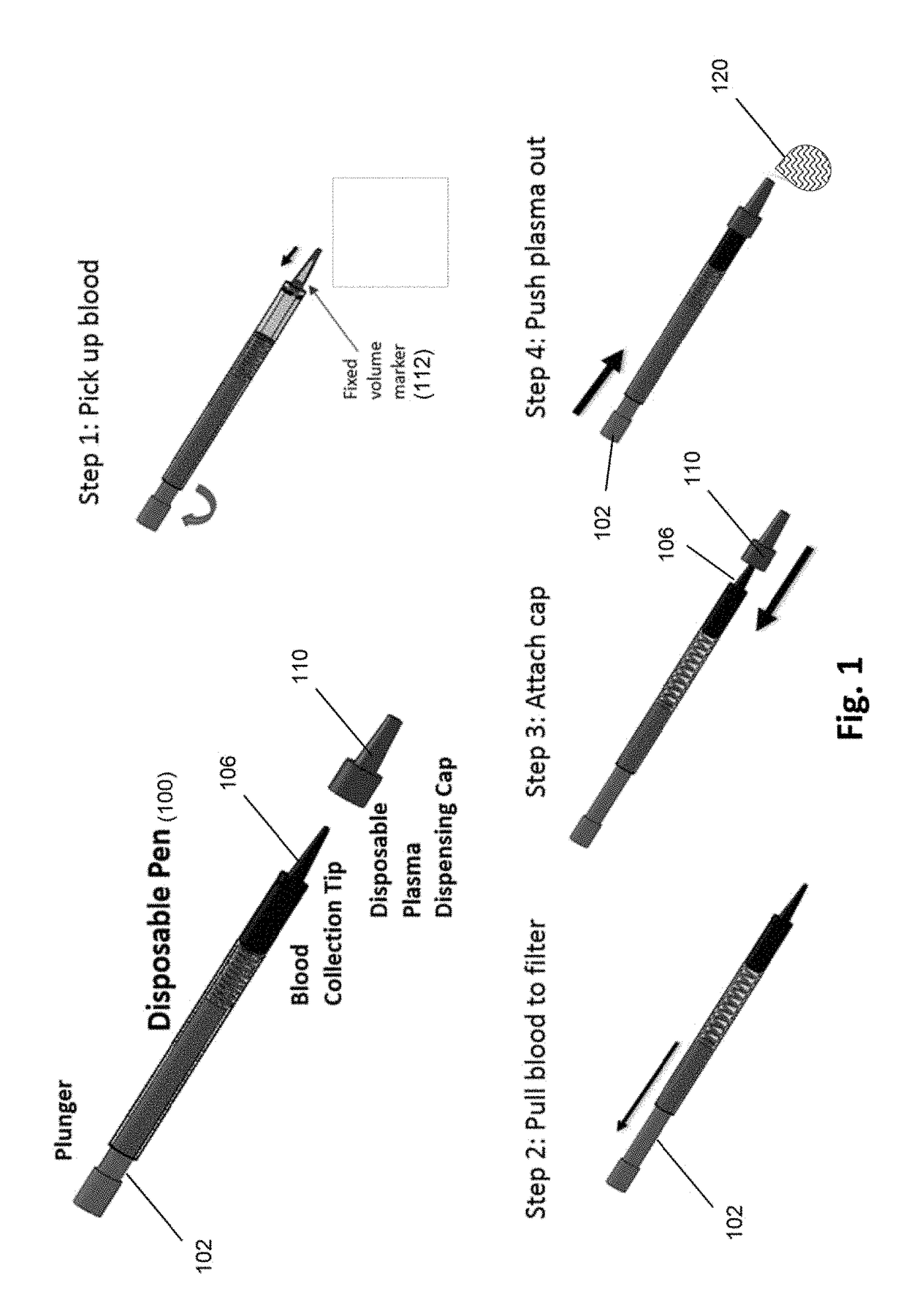
[0050]An exemplary “pen” design of a device of the invention is illustrated in FIG. 1. The pen may include a disposable tip for drawing up blood from the fingertip surface or secondary blood sample container. A spring-loaded plunger draws blood through a filter stack that is integrated inside the tip. A second disposable cap at the end of the tip encloses the blood contaminated tip and seals the entrance end of the tip. The cap contains built-in microfluidic channels. When the plunger is pushed, plasma collected at the end of filter maze is pushed through the channels in the cap and forced out through the tip of the cap, while captured cells remain on the filter surfaces. Some embodiments are configured for viral load assays.

[0051]In one aspect, the invention includes a microscale plasma separation (MPS) device that meets the following performance criteria:

[0052]a) The device processes 30 to 500 μl of blood and ex...

example 2

Spring-Driven Plasma Separator with Multiple Filter Systems

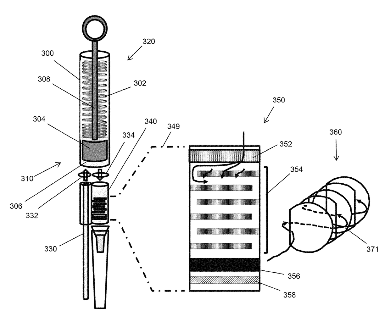
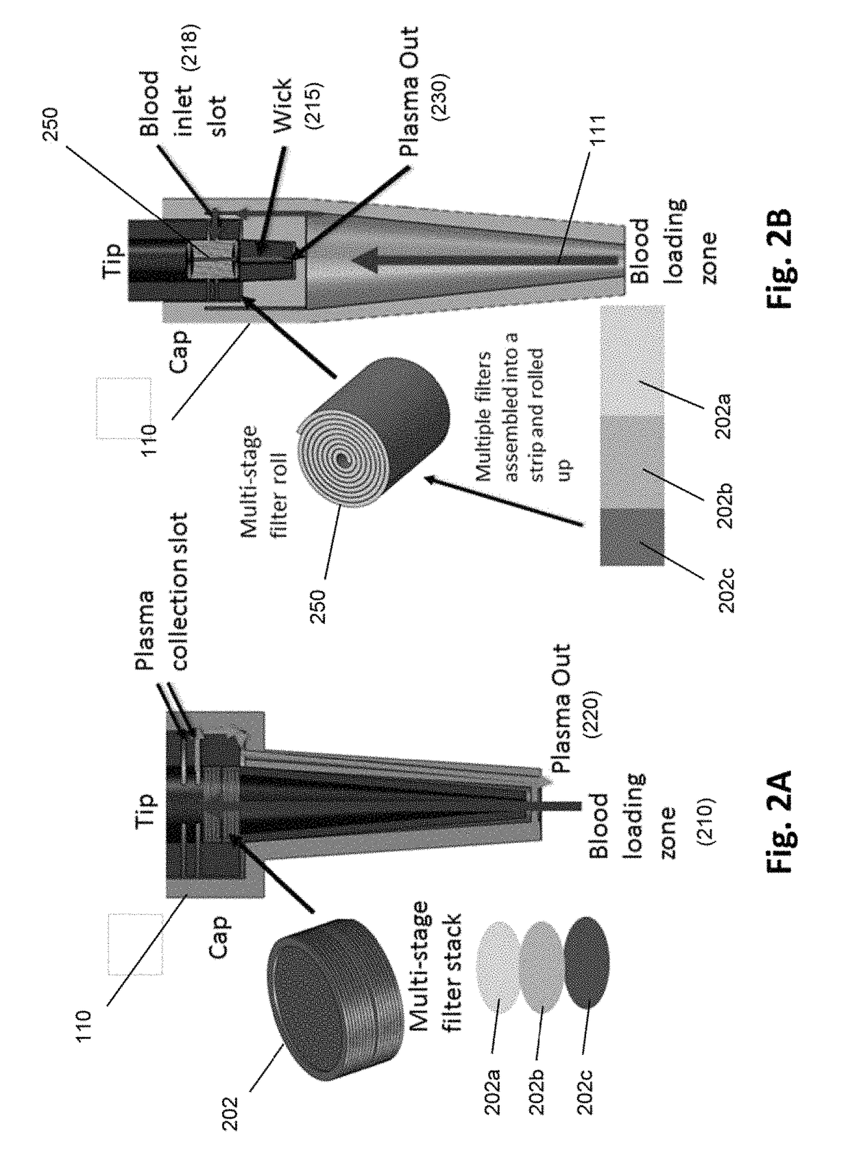
[0070]Components of another embodiment of a microfluidic plasma separator are illustrated in FIG. 3. Cylindrical body (300), having first end (310) and second end (320), contains compression spring (302) and plunger (304) which is moveable along the axis of cylindrical body (300) and which forms a seal with the inner wall of cylindrical body (300), thereby forming sample collection receptacle (306) at first end (310) of cylindrical body (300). Plunger (304) is configured with lever (308) which permits plunger (304) to be manually moved between first end (310) and second end (320). Lever (308) also permits spring (302) to be compressed. Optionally cylindrical body (300) may include a mechanical catch (not shown) to reversibly hold compression spring (302) in a compressed state until it is manually released, which then allows spring (302) to de-compress and push plunger (304) toward first end (310) of cylindrical body (300) wh...

example 3

Screw-Driven Plasma Separator

[0074]As mentioned above, another embodiment of a manually driven pump to deliver substantially constant low pressure to sample is illustrated in FIG. 5A. This embodiment is substantially the same as that of FIG. 3, except that a screw-driven manual pump is substituted for a spring-driven pump. Device (500) comprises sample collection receptacle (502) fluidly connected to inlet tube (504) through port (504) and one-way valve (508). Sample collection chamber (502) is also fluidly connected to filter chamber (512) through one-way valve (514). Sample collection receptacle (502), one-way valves (508 and 514), plunger (520), and inlet tube (504) cooperate as described above to draw in a volume of sample and to drive it into and through filter chamber (512). Filter chamber (512) contains filter and / or filter system (515) and has outlet (518) on downstream side of filter (515). Plunger (520) is sealingly fitted into cylindrical body (525) and rigidly connected ...


PUM

PropertyMeasurementUnit
pressureaaaaaaaaaa
volumeaaaaaaaaaa
flow ratesaaaaaaaaaa

Abstract

The invention is directed to methods and devices for efficient separation of plasma from whole blood which are suitable for point of care use in resource poor environments. In some embodiments, elements of such devices comprise (a) a sample collection receptacle (SCR) with at least one port, the sample collection receptacle capable of holding a predetermined volume of a sample of undiluted whole blood drawn through a port; (b) a filter chamber having an inlet and an outlet, and containing at least one filter capable of separating plasma from blood cells as sample passes from an inlet side to an outlet side of the at least one filter whenever the filter chamber is placed in fluid communication with a port of the sample collection receptacle; and (c) a manually driven pump operationally associated with the SCR and filter chamber for (i) drawing a predetermined volume of sample into the SCR by a first user action and (ii) driving the predetermined volume at a substantially constant linear flow under a pressure not exceeding 2 psi from the SCR through the filter chamber and the outlet of the filter chamber by a second user action.

Description

[0001]This is a continuation application of U.S. patent application Ser. No. 15 / 521,221 filed 21 Apr. 2017 which, in turn, was filed under 35 USC 1.371(f) based on International Application serial number PCT / US2015 / 058731 filed 3 Nov. 2015, which claims priority from U.S. provisional application Ser. No. 62 / 200,572 filed 3 Aug. 2015, and Ser. No. 62 / 074,713 filed 4 Nov. 2014. Each of the foregoing applications is incorporated herein by reference in its entirety.[0002]Blood contains a massive amount of information about the functioning of all tissues and organs in the body. Consequently, blood sampling and analysis are of prime interest for both medical and science applications, and hold a central role in the diagnosis of many physiologic and pathologic conditions. Blood has two main components, plasma and cells, and for a wide range of assays and diagnostic tests, the efficient separation of plasma from cells is highly important.[0003]Many clinical tests and research assays often re...

Claims


Application Information

Patent Timeline
Patent Type & Authority Patents(United States)
IPC IPC(8): B01L1/00A61M1/34A61B5/15A61J1/05G01N33/49B01L3/02B01L3/00
CPCA61M1/3403A61B5/150343A61B5/150244A61B5/150236A61B5/150221A61B5/150022A61J1/05B01L3/502B01L3/0217A61M1/3496A61M1/34G01N33/491A61M2205/3331B01L2300/0832B01L2300/0681B01L2200/10B01L2200/0605A61J1/06
Inventor TAN, MINGZAUGG, FRANKKERNEN, PETER
Owner WAINAMICS INC
Learn More