Power supply unit and static eliminator

a power supply unit and static eliminator technology, applied in the direction of electrostatic charges, power conversion systems, electrical apparatus, etc., can solve the problems of increasing the size the complexity of the control and circuit configuration, and the significant cost of the static eliminator, so as to improve the balance of ions, increase the lifetime of the ion generator, and improve the effect of ion balan

Active Publication Date: 2018-12-04
MURATA MFG CO LTD
View PDF25 Cites 0 Cited by
  • Summary
  • Abstract
  • Description
  • Claims
  • Application Information

AI Technical Summary

Benefits of technology

[0008]Accordingly, the positive and negative voltage peak values at the secondary side of the transformer are varied due to the capacitor electrically connected to the secondary winding, and thus the total amount of current output from the positive-side output terminal is able to be equal or substantially equal to the total amount of current output from the negative-side output terminal. As a result, since it is not necessary to perform the feedback control and so on, positive current and negative current are able to be balanced or substantially balanced with one another with simple circuitry.
[0012]Accordingly, the voltage of the capacitor is able to be detected with the resistive voltage divider. As a result, the output voltage is able to be monitored and any abnormal condition of the power supply unit is able to be detected.
[0020]Accordingly, the output voltage is able to be shared between the multiple secondary windings to significantly reduce withstanding voltage performance of each secondary winding.
[0024]Accordingly, since the current flowing into the positive ion generator is equal or substantially equal to the current flowing into the negative ion generator, the static eliminator is able to provide a desirable balance of generation of the positive and negative ions.
[0026]Accordingly, the positive and negative ions are able to be alternately generated from one ion generator. If the positive ions are constantly or substantially constantly discharged from a single ion generator, there is a problem in that the balance of the ions is disturbed near the ion element. In addition, there is a problem in that the ion generator is abraded due to collision of molecules in the positive ion generator. If the negative ions are constantly or substantially constantly discharged from a single ion generator, there is also a problem in that siloxane adheres to the ion generator. Accordingly, alternately generating the positive and negative ions from the ion generator resolves the problems described above, thus providing a significant improvement of the balance of the ions near the ion element and an increase of the lifetime of the ion generator.
[0027]According to preferred embodiments of the present invention, since it is not necessary to perform the feedback control and so on, the positive current and the negative current are able to be balanced or substantially balanced with one another with simple circuitry. In addition, since it is not necessary to feedback-control the positive voltage and the negative voltage, the cost and the size are able to be significantly reduced. Furthermore, the connection of the positive ion generator and the negative ion generator to the positive-side output terminal and the negative-side output terminal provides a static eliminator with an excellent balance of generation of the positive and negative ions.

Problems solved by technology

However, in Japanese Patent Application No. 4367580, since feedback control is performed so as to keep the balance of generation of the positive and negative ions, there is a problem in that the control and the circuit configuration are complicated.
In addition, since it is necessary to provide two output circuits in order to control positive voltage and negative voltage, there is a problem in that the static eliminator involves a significant cost and is increased in size.

Method used


Image

  • Power supply unit and static eliminator
  • Power supply unit and static eliminator
  • Power supply unit and static eliminator

Examples


first preferred embodiment

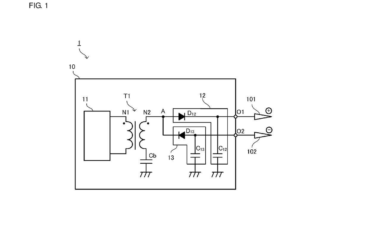
[0044]FIG. 1 is a circuit diagram of a static eliminator 1 according to a first preferred embodiment of the present invention.

[0045]The static eliminator 1 includes a power supply unit 10, a positive ion generator 101, and a negative ion generator 102. The power supply unit 10 includes a positive-side output terminal O1 and a negative-side output terminal O2. The power supply unit 10 outputs positive high voltage (hereinafter referred to as positive voltage) from the positive-side output terminal O1 and outputs negative high voltage (hereinafter referred to as negative voltage) from the negative-side output terminal O2. The positive-side output terminal O1 is an example of a “positive-side output terminal”. The negative-side output terminal O2 is an example of a “negative-side output terminal”.

[0046]The positive ion generator 101 is electrically connected to the positive-side output terminal O1. The negative ion generator 102 is electrically connected to the negative-side output ter...

second preferred embodiment

[0077]FIGS. 10A to 10C are circuit diagrams of static eliminators 2A, 2B, and 2C, respectively, according to a second preferred embodiment of the present invention. The static eliminators 2A and 2B each include a resistive voltage divider circuit that detects output voltage.

[0078]In the case of the static eliminator 2A shown in FIG. 10A, a series circuit of resistor dividers R31 and R32 is electrically connected in parallel to the bypass capacitor Cb. The series circuit of the resistor dividers R31 and R32 enables detection of the voltage of the bypass capacitor Cb. If the voltage between both ends of the resistor divider R32 is denoted by Vm, the voltage Vb of the bypass capacitor Cb is represented by Vb≈(R31+R32) / R32*Vm. Accordingly, the voltage between both ends of the bypass capacitor Cb is able to be measured at low voltage.

[0079]When the input voltage is denoted by V1, the voltage generated at the secondary side of the transformer T1 is denoted by V2, the number of turns of th...

third preferred embodiment

[0083]FIG. 11 is a circuit diagram of a static eliminator 3 according to a third preferred embodiment of the present invention.

[0084]The static eliminator 3 includes a power supply unit 10C. The power supply unit 10C includes two positive-side output terminals O1 and O3 and two negative-side output terminals O2 and O4. Positive ion generators 101 and 103 are electrically connected to the positive-side output terminals O1 and O3, respectively, and negative ion generators 102 and 104 are electrically connected to the negative-side output terminals O2 and O4, respectively. Multiple positive ion generators 101 and 103 may be electrically connected to the positive-side output terminals O1 and O3, respectively, and multiple negative ion generators 102 and 104 may be electrically connected to the negative-side output terminals O2 and O4, respectively.

[0085]The power supply unit 10C includes the driving circuit 11, a transformer T2, positive-side rectification circuits 12 and 14, and negati...


PUM


Abstract

A power supply unit includes a transformer including a primary winding that receives an alternating-current voltage and a secondary winding including a first end electrically connected to ground, a positive-side rectification circuit including a diode electrically connected to a second end of the secondary winding, an anode of which is electrically connected to the second end, and a cathode of which is electrically connected to a positive-side output terminal, a negative-side rectification circuit including a diode electrically connected to the second end of the secondary winding, a cathode of which is electrically connected to the second end, and an anode of which is electrically connected to a negative-side output terminal, and a capacitor provided on a path from a node between the second end of the secondary winding and the positive-side rectification circuit and the negative-side rectification circuit to the ground through the secondary winding.

Description

CROSS REFERENCE TO RELATED APPLICATIONS[0001]This application claims the benefit of priority to Japanese Patent Application No. 2015-106263 filed on May 26, 2015 and is a Continuation Application of PCT Application No. PCT / JP2016 / 061346 filed on Apr. 7, 2016. The entire contents of each application are hereby incorporated herein by reference.BACKGROUND OF THE INVENTION1. Field of the Invention[0002]The present invention relates to a power supply unit that outputs positive current and negative current in a balanced or substantially balanced manner and a static eliminator including the power supply unit.2. Description of the Related Art[0003]Static eliminators include, for example, a static eliminator that applies a method of concentrating an electric field on a needle discharge electrode to generate positive and negative ions and eliminating the static electricity with ionized air. Since an object is charged if the amount of generation of the ions is biased toward the positive or neg...

Claims


Application Information

Patent Timeline
Patent Type & Authority Patents(United States)
IPC IPC(8): H02M7/06H05F3/04H01T23/00
CPCH02M7/062H05F3/04H01T23/00H05F3/06
Inventor KUROKAWA, TAKASHI
Owner MURATA MFG CO LTD
Why Eureka
Try Eureka